Bridging system for off-module studs

Inactive Publication Date: 2002-05-23
CLARKWESTERN DIETRICH BUILDING SYST
View PDF16 Cites 31 Cited by
  • Summary
  • Abstract
  • Description
  • Claims
  • Application Information

AI Technical Summary

Benefits of technology

0018] Another embodiment of the present invention also provides an angled clip having a first portion with a cross-section generally similar to the cross section of the bridging/spacing member and a second portion lying in a plate extending approximately at a right angle to the first portion for attachment to the face of a wall or stud without passing through a conduit punch-out. The present invention may also provide a jamb connector for engaging the webs of two adjacent metal studs and for connection to bridging/spacing members on either side. The present invention may also include a hold down bracket attachable above a bridging/spacing member across a conduit punch-out to prevent removal of the bridging/spacing member.
0019] Still another embodiment of the present invention comprises a stud bridging/spacing member for the quick and easy spacing of a plurality of studs without measuring, while at the same time providing bridging between the studs. In this embodiment, the bridging function of the stud bridging/spacing member reinforces the studs to resist bending under axial loads and to resist

Problems solved by technology

These loads may cause flexing (including bowing, twisting or other deformation of the stud) or turning of the metal studs which may cause the walls to crack or otherwise be flawed or damaged.
In load bearing walls, this problem is structural as well as aesthetic.
The installation of metal stud wall systems, including the reinforcing bridging systems, heretofore has been a time consuming process.
Because of the time consuming nature of the installation process, fasteners can be missed or forgotten.
In the welded channel bridging systems, welders and their equipment are relatively expensive, and welds also can be missed, or can be improperly form

Method used


Image

  • Bridging system for off-module studs
  • Bridging system for off-module studs
  • Bridging system for off-module studs

Examples


Example

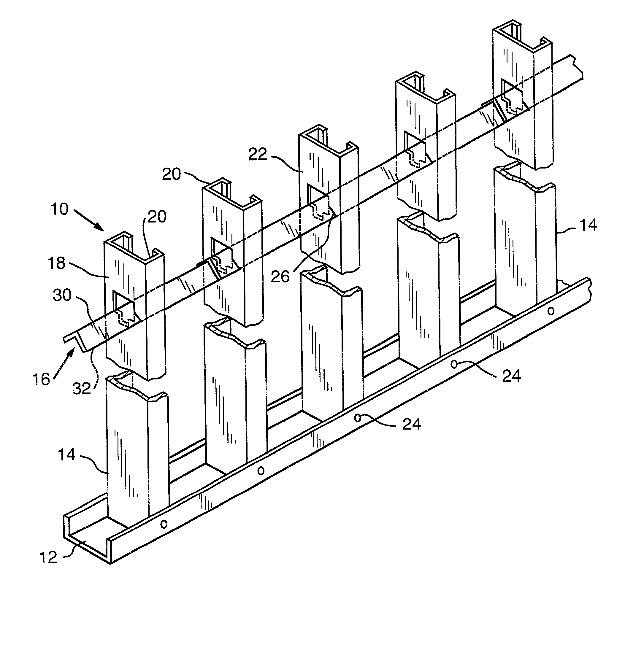
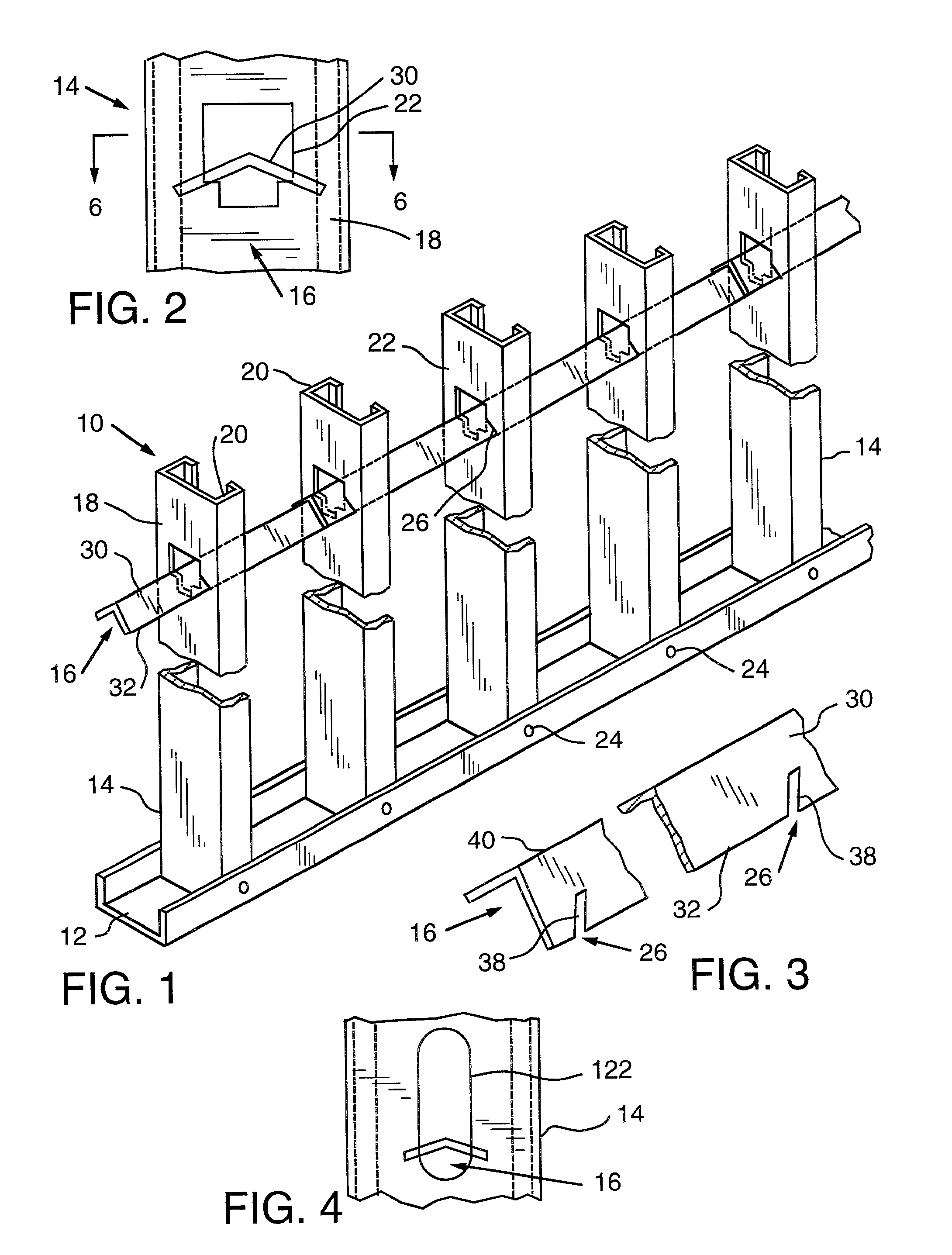
[0057] FIG. 1 illustrates the skeleton of a metal stud wall 10 according to one embodiment of the present invention. In this embodiment, the metal stud wall 10 generally comprises a base track 12, a plurality of metal studs 14 disposed in a row, at least one bridging / spacing member 16, and wall panels (not shown). The wall panels, such as wall board, may be secured in a well known manner to one or both sides of the metal studs to close the wall and to form the exterior surface or surfaces of the wall. Alternatively, one or both sides of the metal studs may be faced with masonry, such as a brick wall facing on an exterior side of a curtain wall.

[0058] The studs 14, as illustrated in FIG. 1, are generally C-shaped, as is conventional. The studs 14 have a web 18 and a pair of L-shape flanges 20 perpendicular to the web 18. There is also one or more openings 22 in the web 18. The openings 22 heretofore have been provided in metal studs to permit bridging members, electrical conduit and / ...


PUM

PropertyMeasurementUnit
Angleaaaaaaaaaa
Angleaaaaaaaaaa
Widthaaaaaaaaaa

Abstract

A metal stud wall and method of assembling the same are characterized by a stud bridging/spacing member generally having at least three longitudinally spaced apart notches for receiving and engaging therein a web of a metal stud. The notches extend at an incline to the longitudinal axis of the elongate member. In the assembly of a metal stud wall having a row of metal studs each having at least two flanges interconnected by a web, the stud bridging/spacing member is inserted through aligned openings in the webs of three or more studs and the webs are engaged in the notches to position and hold the metal studs at a prescribed spacing. Successive bridging/spacing members may be inserted through further studs and overlapped with the preceding bridging/spacing member, and engaging a common stud, to position and hold the studs at the prescribed spacing. The stud bridging/spacing member not only spaces the studs, but reinforces the studs against deflection and rotation caused by transverse, axial and lateral loading.

Description

[0001] This non-provisional application for patent claims priority from U.S. Provisional Patent Application Serial No. 60 / 229,583, Filed Aug. 31, 2000.FEDERALLY SPONSORED RESEARCH[0002] Not applicable.[0003] 1. Field of the Invention[0004] The invention herein described relates generally to stud wall systems and more particularly to a device for spacing and bridging studs in a stud wall, and connecting devices for use with spacing and bridging members.[0005] 2. Description of the Invention Background[0006] Metal studs are used to form walls in building structures today, including load bearing walls such as exterior walls and curtain walls. In a typical installation, the metal studs are secured by screws at their lower ends to a bottom track secured to a floor, and extend at their upper ends into a top track secured to overhead joists which may form the framework for an upper floor. The upper ends of the studs generally also are secured to the top track. Exterior wall materials and / o...

Claims


Application Information

Patent Timeline
IPC IPC(8): E04B2/58E04B2/74E04B2/76
CPCE04B2/58E04B2/7457Y10T403/7073Y10T428/1241E04B2/763
Inventor ELDERSON, WILLIAM L.
Owner CLARKWESTERN DIETRICH BUILDING SYST
Why Eureka
Try Eureka