Radiation Source

a radiation source and lithographic technology, applied in the field of lithographic apparatus, can solve the problems of inability to predict with absolute certainty, the relationship between the and the measured intensity/intensity distribution of the radiation output by the radiation producing plasma, etc., and achieve the goal of predicting the relative alignment between the fuel and the focus of the radiation directed at the fuel with a high degree of accuracy

Inactive Publication Date: 2015-09-17
ASML NETHERLANDS BV
View PDF0 Cites 13 Cited by
  • Summary
  • Abstract
  • Description
  • Claims
  • Application Information

AI Technical Summary

Benefits of technology

The invention relates to an apparatus for controlling the flow of liquid fuel during operation. A mechanism can move the tip of a sprayer that releases the fuel, which affects how it spreads out from its initial point of contact with the surface being coated. This allows better control over the pattern of fuel drops, resulting in more precise application.

Problems solved by technology

The technical problem addressed in this patent text relates to accurately identifying the position of the fuel and its impact on the overall performance of the lithographic apparatus during exposure to radiation. Current methods involve measuring the properties of the radiation output by the reaction generating plasma, but this measurement depends heavily on the interactions between the fuel and the plasma. Additionally, previous pulses of radiation may influence subsequent measurements, leading to potential errors and reduced efficiency of the system.

Method used


Image

  • Radiation Source
  • Radiation Source
  • Radiation Source

Examples


Embodiment Construction

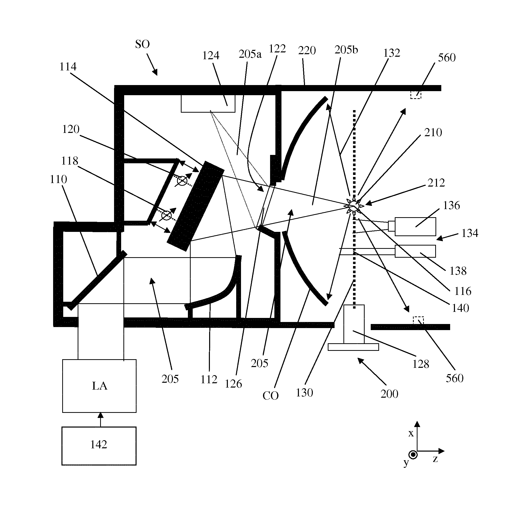
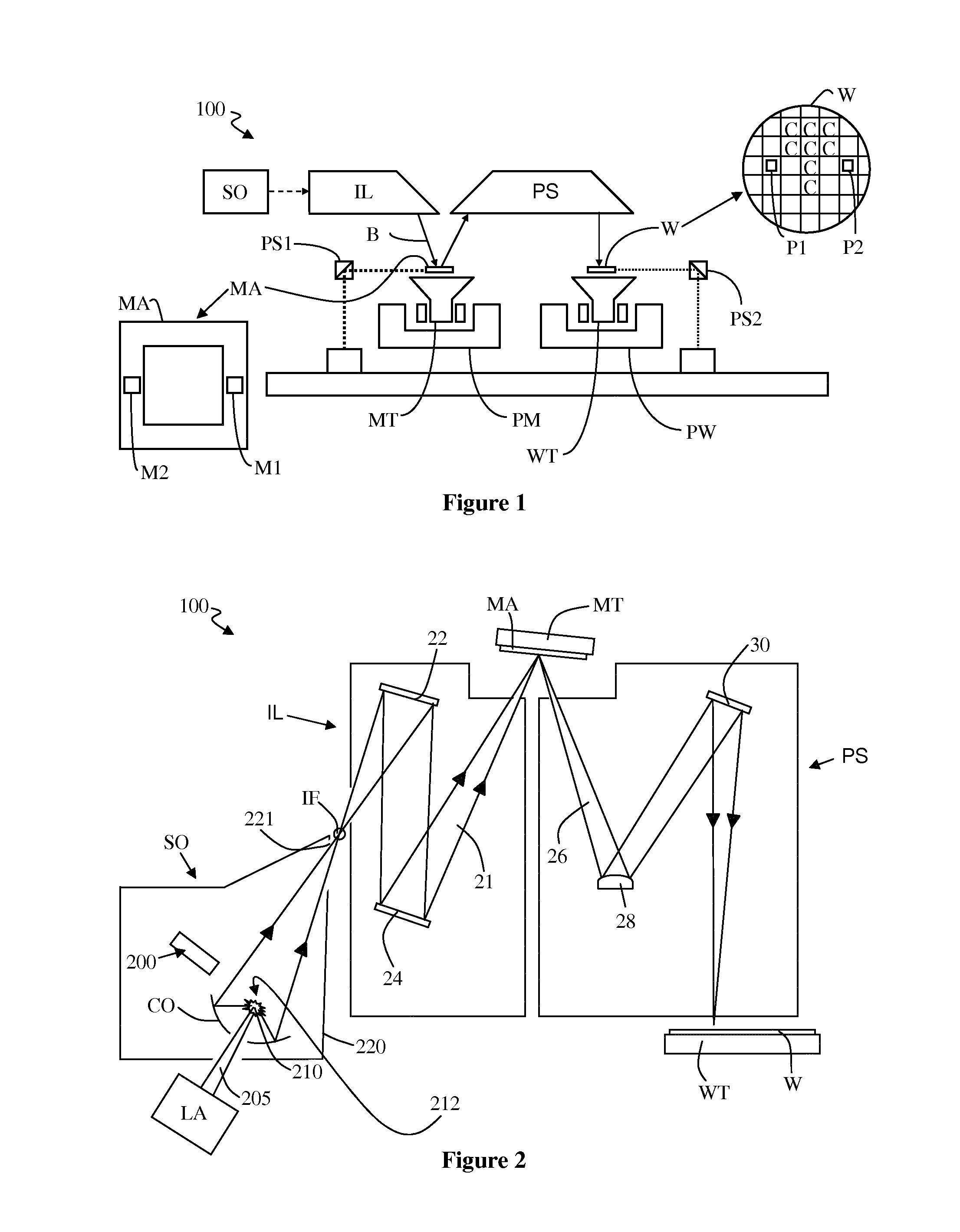
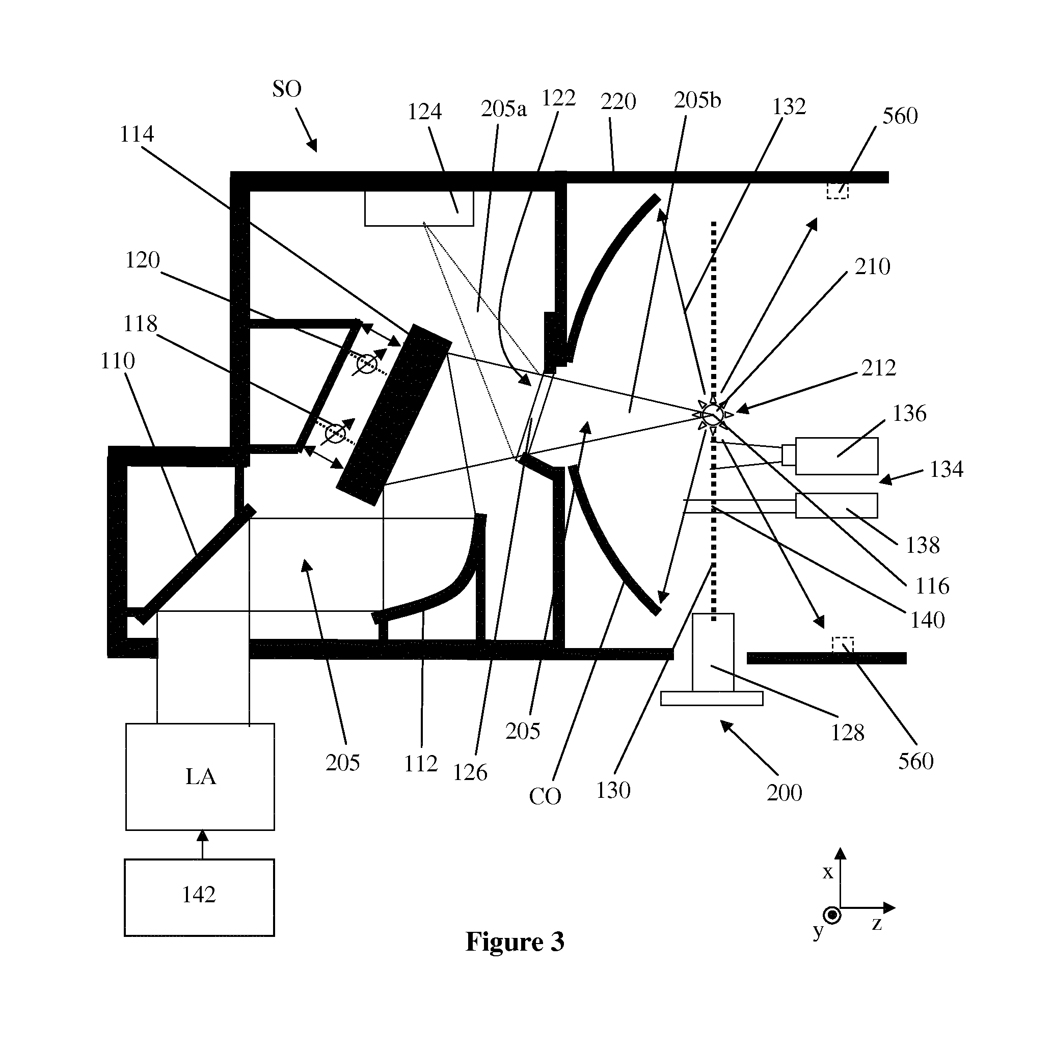
[0055]FIG. 1 schematically depicts a lithographic apparatus 100 including a source collector module SO according to one embodiment of the invention. The apparatus comprises:[0056]an illumination system (illuminator) IL configured to condition a radiation beam B (e.g., EUV radiation).[0057]a support structure (e.g., a mask table) MT constructed to support a patterning device (e.g., a mask or a reticle) MA and connected to a first positioner PM configured to accurately position the patterning device;[0058]a substrate table (e.g., a wafer table) WT constructed to hold a substrate (e.g., a resist-coated wafer) W and connected to a second positioner PW configured to accurately position the substrate; and[0059]a projection system (e.g., a reflective projection system) PS configured to project a pattern imparted to the radiation beam B by patterning device MA onto a target portion C (e.g., comprising one or more dies) of the substrate W.

[0060]The illumination system may include various typ...


PUM


Abstract

A radiation source suitable for providing a beam of radiation to an illuminator of a lithographic apparatus. The radiation source comprises a nozzle configured to direct a stream of fuel droplets along a trajectory towards a plasma formation location. The radiation source is configured to receive a first amount of radiation such that, in use, the first amount of radiation is incident on a fuel droplet at the plasma formation location, and such that, in use, the first amount of radiation transfers energy to the fuel droplet to generate a radiation generating plasma that emits a second amount of radiation. The radiation source further comprises a first sensor arrangement configured to measure a property of the first amount of radiation that is indicative of a focus position of the first amount of radiation; and a second sensor arrangement configured to measure a property of a fuel droplet that is indicative of a position of the fuel droplet.

Description


Claims


Application Information

Patent Timeline
Owner ASML NETHERLANDS BV
Why Eureka
Try Eureka