Positionable Foot Portion of a Medical Device

Active Publication Date: 2019-08-15
BORCAD MEDICAL AS
View PDF9 Cites 1 Cited by
  • Summary
  • Abstract
  • Description
  • Claims
  • Application Information

AI Technical Summary

Benefits of technology

The present invention provides a method for easily moving a foot portion of a medical device into a required position without limiting the actions of medical personnel. The foot portion can be moved horizontally and vertically using a movement mechanism that allows for quick and effective positioning without protruding undesirably. The movement mechanism includes a horizontal parallelogram or a scissor mechanism, and a vertical movement mechanism such as a parallelogram or a scissor mechanism. The foot portion is connected to the movement mechanisms through a lockable spring that allows for easy adjustment and positioning of the foot portion. The movement mechanisms are controlled by controllers and lockable springs, making the movement of the foot part easier for medical personnel. Overall, the invention provides a more efficient and comfortable method for medical procedures that require positioning of the foot portion.

Problems solved by technology

This solution requires intervention of medical personnel as well as space for storing the foot portion, which interferes with the course of the medical procedure.
This limits the range of utilization of the medical bed.
Rotation causes protrusion into the operating space.
In the present state of the art, there are no available solutions for foot portion of medical beds, which would allow moving the foot portion under the bed without the limiting protrusion into the operating space.

Method used


Image

  • Positionable Foot Portion of a Medical Device
  • Positionable Foot Portion of a Medical Device
  • Positionable Foot Portion of a Medical Device

Examples


Embodiment Construction

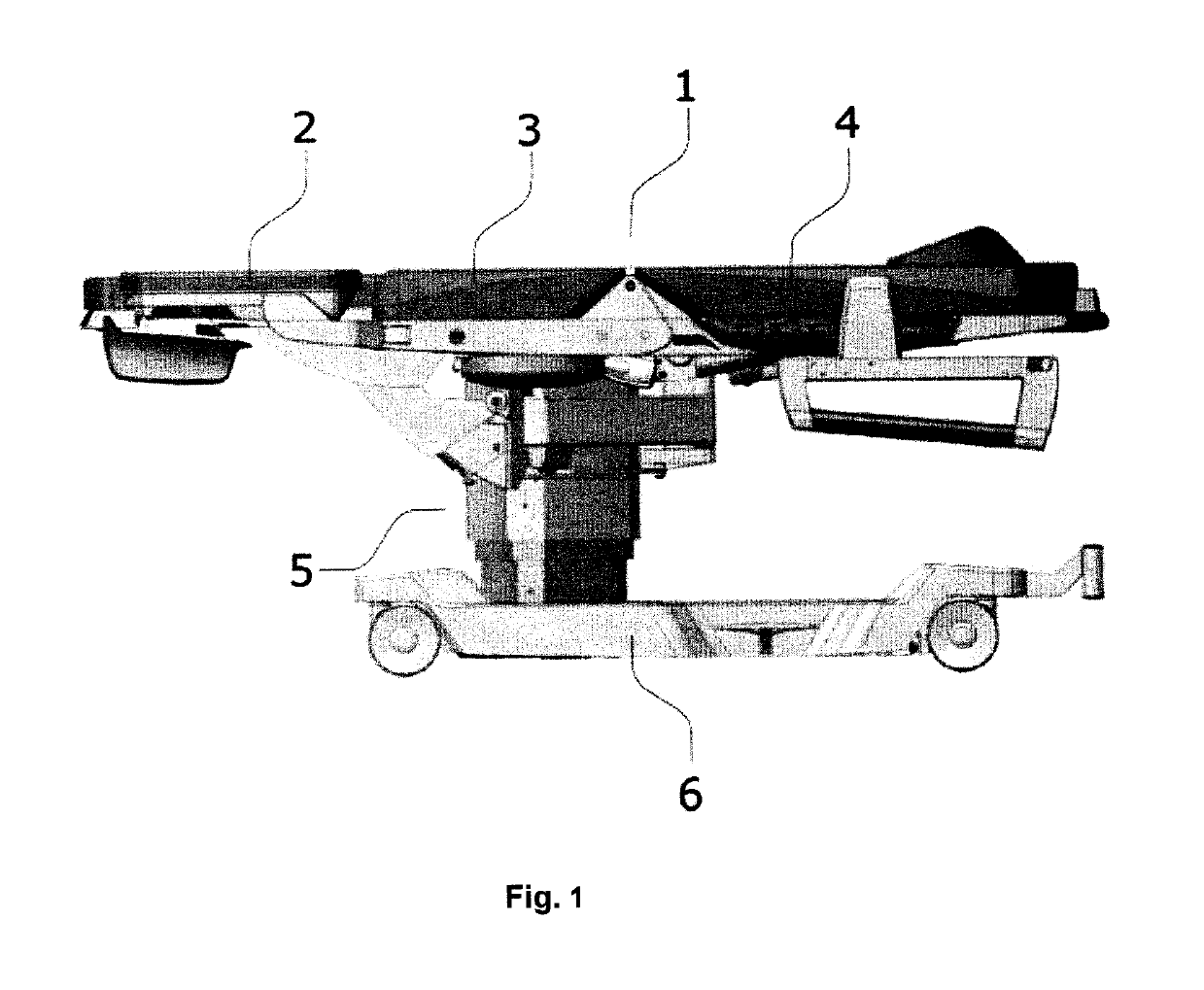
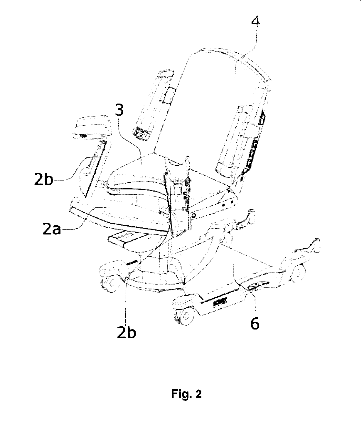
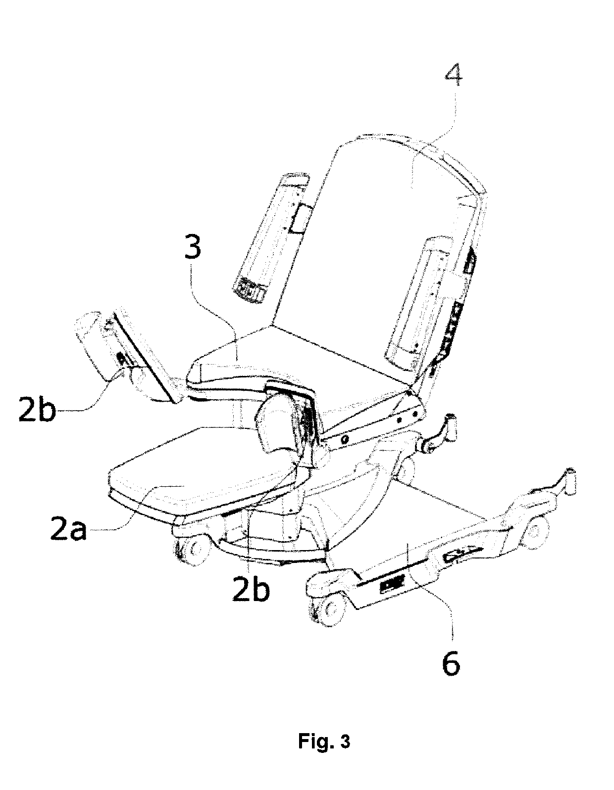
[0021]An exemplary embodiment of the invention is a medical device for, e.g. gynecological examination bed or a birthing bed, as it is illustrated in the FIG. 1. A part of the medical device is an upper rest area, which is arranged e.g. on a column 5 or a scissor lift, provided on a chassis 6. A column drive may consist of one or more telescopic segments.

[0022]The column 5 may consist of more concentric segments, where each of them, except the column arranged nearest to the chassis frame, comprise a motor intended for driving a particular segment.

[0023]Part of the upper support area is a detachable rest area 1. The rest area 1 is adapted for easy maintenance. The rest area 1 may be, for example, a layer of soft material for interaction with the patient's body. The rest area may consist of, for example, foamed polyurethane, cold foam or a combination thereof. The foam layer may be provided in a washable shell.

[0024]The chassis frame comprises wheels. At least three wheels, preferably...


PUM


Abstract

The object of the invention is a foot portion (2a) of a medical device, such as gynecological examination bed or a birthing bed. The aim of the invention is to provide a method for moving the foot portion into the required position quickly, effectively and not limiting the actions of medical personnel. An advantage of the present invention is moving the foot portion under the rest area (1) without undesirable protrusion. Movement of the foot portion (2a) under the rest area (1) is performed around a column (5), which is attached under the side edge of a seating portion (3). Such arrangement of the column leaves free space under the rest area (1) for moving the foot portion (2a). Movement of the foot portion (2a) is performed with minimum protrusion over the borderline of the rest area (1) by means of a parallelogram. The foot portion according to the present invention may be also positioned horizontally and vertically, according to the patient's need during the procedure. For each movement, there are available separate moving mechanisms and latching mechanisms.

Description

FIELD OF THE INVENTION[0001]The technical solution is related to medical devices, such as beds and chairs used in obstetrics, surgery, oncology, gynecology, dialysis and further, for example, hospital beds, transport beds or operating tables, using a telescopic support column allowing change of the height position of the device.BACKGROUND OF THE INVENTION[0002]According to the present state of the art, the foot portion is attached to the structure of medical beds in movable manner in order to optionally adjust the position of the foot portion in relation to the rest part. The foot portion may be detachable from the medical bed, thus enlarging the operating space (area serving for medical personnel to perform the medical act, not being constrained by the medical bed or any of its parts) or it may be its integral part. In some embodiments, it is possible to remove the fixedly attached foot portions from the foot area by moving them out of the operating space, achieving the same effect...

Claims


Application Information

Patent Timeline
IPC IPC(8): A61G13/12A61G13/00A61G13/08
CPCA61G13/125A61G13/0009A61G13/08A61G13/1245A61B2090/506B43L13/00B25J3/02
Inventor MIL, PETRCHLOPCIK, TOMAS
Owner BORCAD MEDICAL AS
Why Eureka
Try Eureka