Ink transfer member position adjusting method and apparatus of rotary stencil printing press

Inactive Publication Date: 2008-07-31
KOMORI CORP
View PDF7 Cites 2 Cited by
  • Summary
  • Abstract
  • Description
  • Claims
  • Application Information

AI Technical Summary

Benefits of technology

[0021]According to the ink transfer member position adjusting method and apparatus of a rotary stencil printing press concerned with the present invention, fine adjustment of the throw-on position of the ink transfer member with respect to the stencil printing plate can be automated by motor driving to lessen burden on the operator and cut down on the adjusting time, thereby increasing the rate of operation and decreasing wasted paper.

Problems solved by technology

Thus, the operator is burdened, and may have to repeat motions, such as manual adjustment in the rotary screen printing unit, followed by confirmation of the resulting product, further followed by manual adjustment in the rotary screen printing unit.
As noted here, the adjustment operation takes time, posing the problem that a large amount of wasted paper occurs.
Moreover, the squeegee or the doctor roller in the rotary screen printing press always contacts the screen printing forme (i.e., its inner peripheral surface) during printing, and is thus worn.
Repeated fine adjustment has resulted in a decreased rate of operation, and has aroused the problem of wasted paper occurrence.

Method used


Image

  • Ink transfer member position adjusting method and apparatus of rotary stencil printing press
  • Ink transfer member position adjusting method and apparatus of rotary stencil printing press
  • Ink transfer member position adjusting method and apparatus of rotary stencil printing press

Examples


embodiment 1

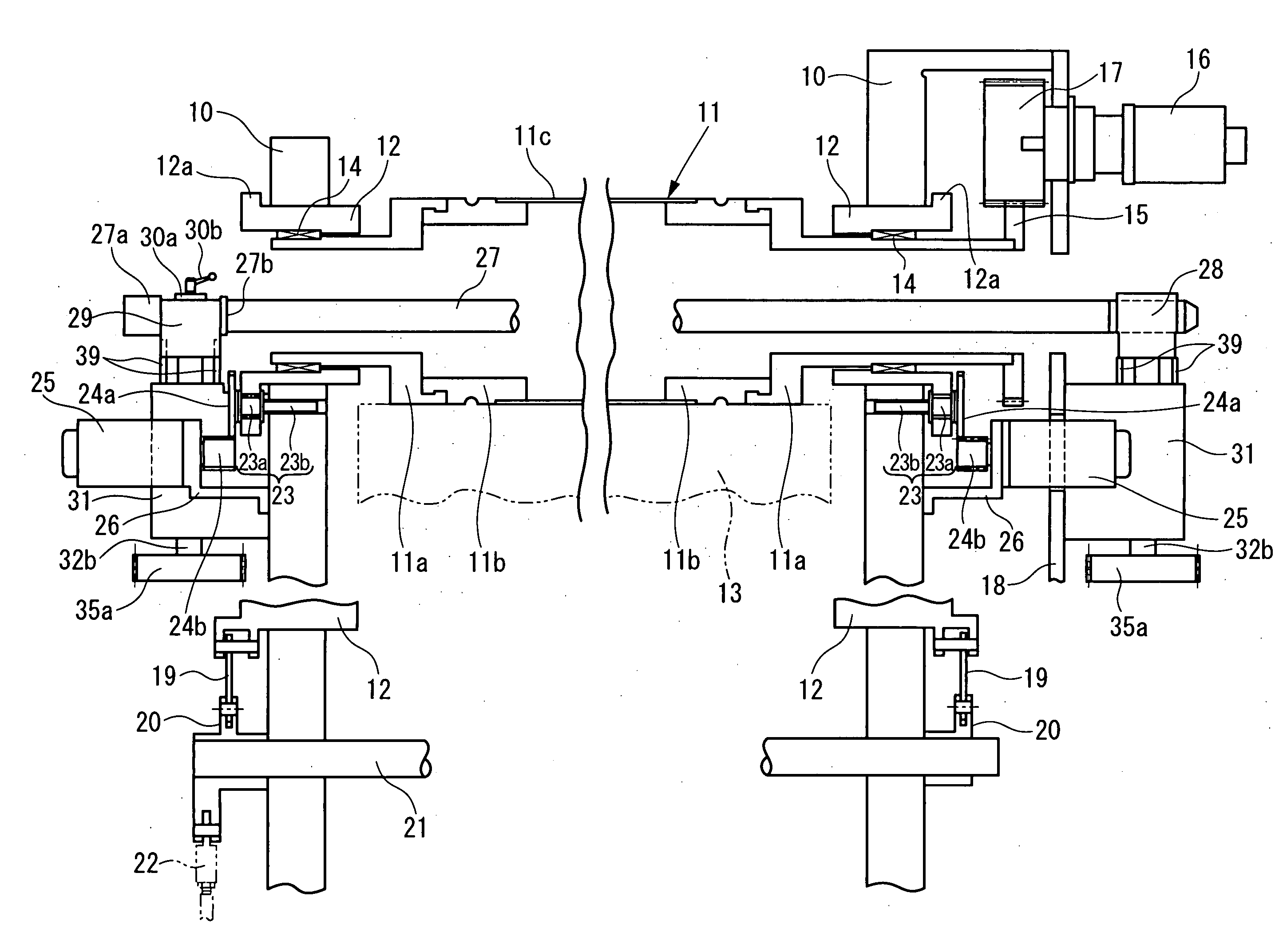
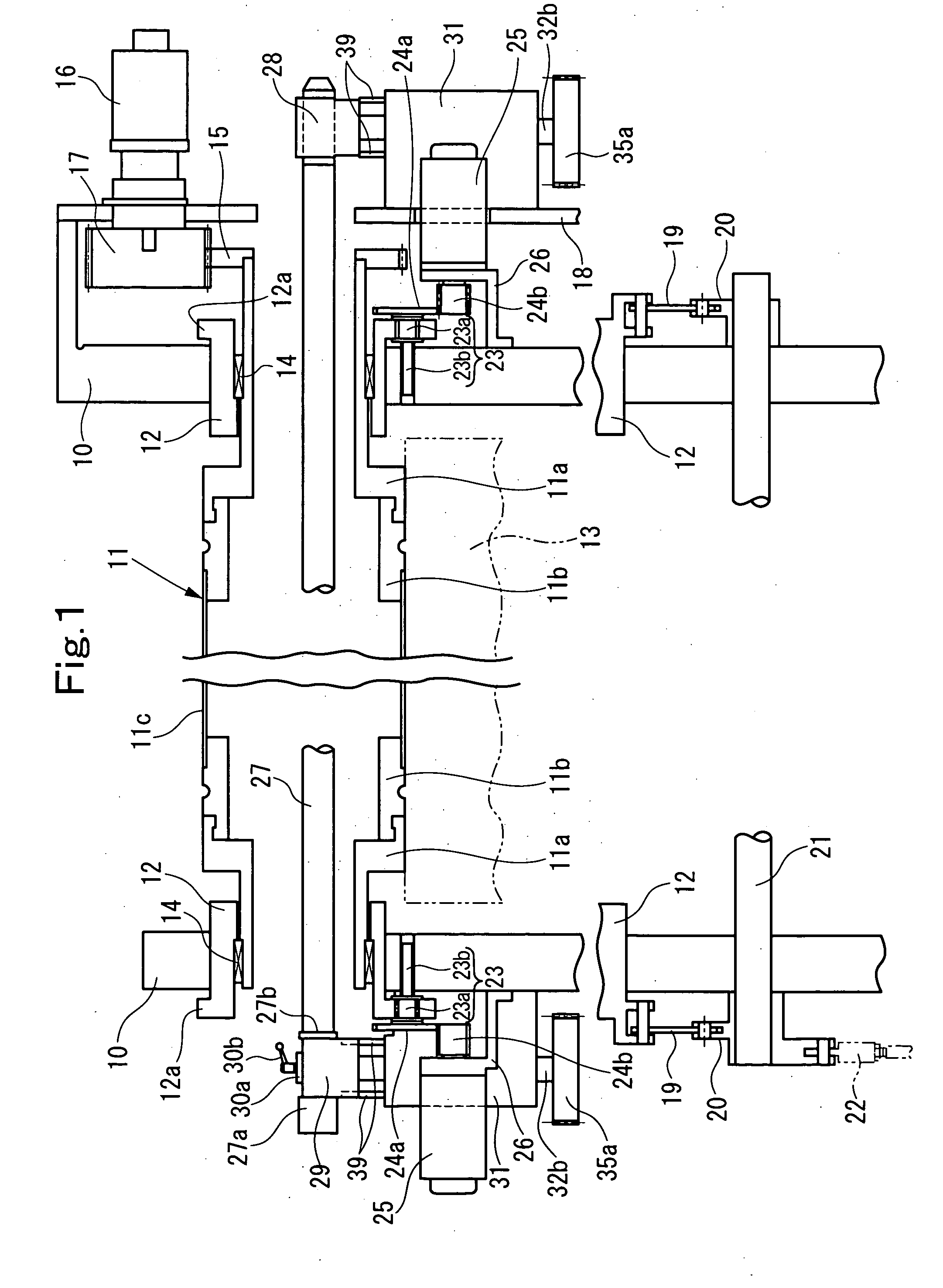
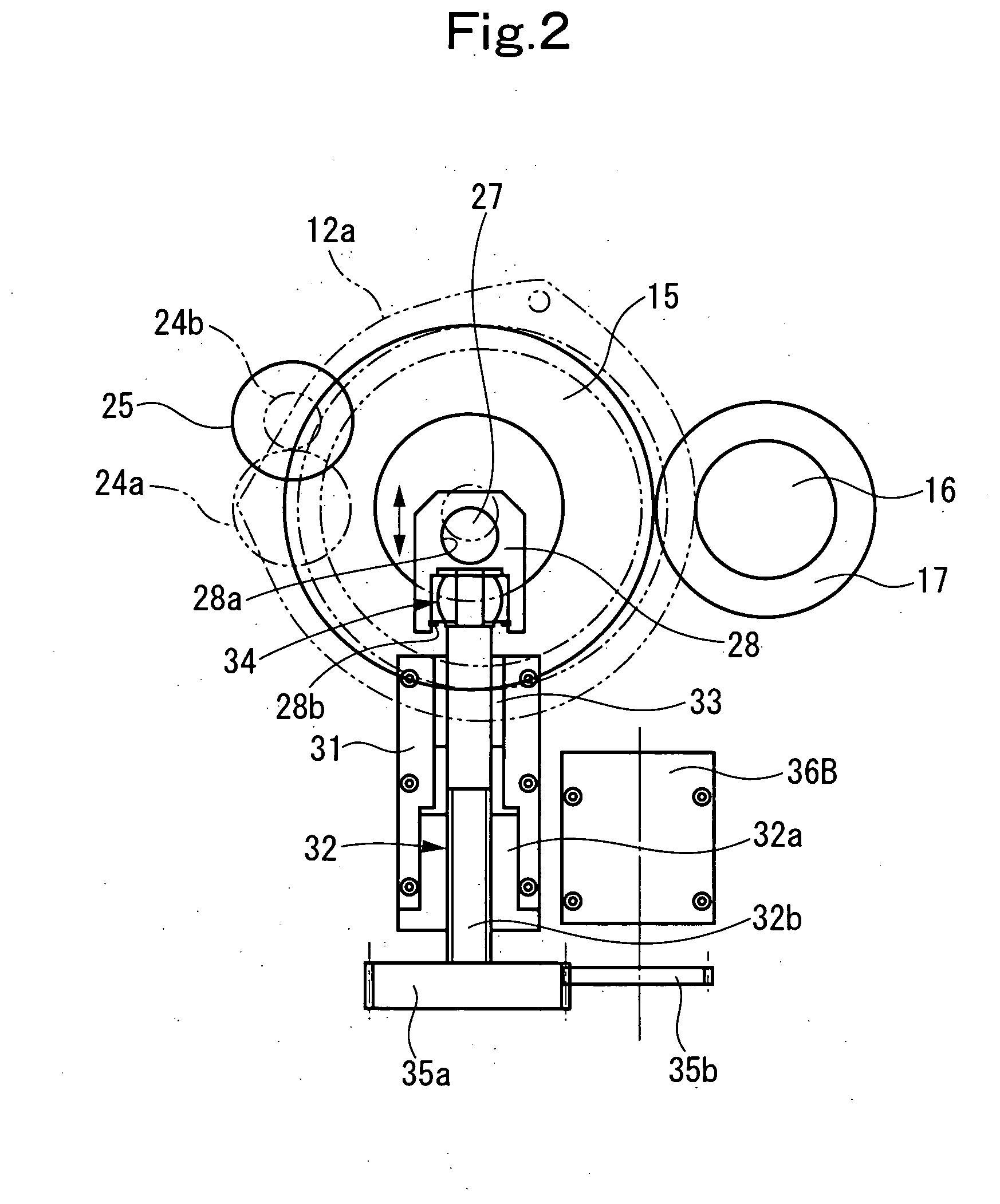
[0094]FIG. 1 is a schematic configurational sectional view of a rotary screen printing unit in a rotary screen printing press showing Embodiment 1 of the present invention. FIG. 2 is a right side view of the rotary screen printing unit in FIG. 1. FIG. 3 is a left side view of the rotary screen printing unit in FIG. 1. FIGS. 4(a) and 4(b) are operating state views. FIGS. 5(a) and 5(b) are control block diagrams of a control device. FIGS. 6(a) to 6(d) are motion flow charts of the control device. FIGS. 7(a) to 7(d) are motion flow charts of the control device. FIG. 8 is a motion flow chart of the control device. FIGS. 9(a) to 9(d) are motion flow charts of the control device. FIGS. 10(a) to 10(d) are motion flow charts of the control device. FIGS. 11(a) to 11(e) are motion flow charts of the control device. FIGS. 12(a) to 12(d) are motion flow charts of the control device.

[0095]In the rotary screen printing unit in the rotary screen printing press (rotary stencil printing press), as s...

embodiment 2

[0332]FIG. 13 is a schematic configurational sectional view of a rotary screen printing unit in a rotary screen printing press showing Embodiment 2 of the present invention. FIG. 14(a) is an explanation drawing of an ink supply system. FIG. 14(b) is an explanation drawing of an ink supply pipe. FIGS. 15(a) and 15(b) are control block diagrams of a control device. FIGS. 16(a) and 16(b) are motion flow charts of the control device. FIGS. 17(a) to 17(c) are motion flow charts of the control device. FIGS. 18(a) to 18(d) are motion flow charts of the control device. FIGS. 19(a) to 19(c) are motion flow charts of the control device. FIG. 20 is a motion flow chart of the control device. FIGS. 21(a) to 21(d) are motion flow charts of the control device. FIGS. 22(a) to 22(d) are motion flow charts of the control device. FIGS. 23(a) to 23(d) are motion flow charts of the control device. FIGS. 24(a) to 24(c) are motion flow charts of the control device. FIGS. 25(a) to 25(d) are motion flow cha...


PUM


Abstract

In a rotary stencil printing press including a rotary screen cylinder which supports a screen printing forme and is supported rotatably, and a squeegee which is located within the rotary screen cylinder and, when printing is done, contacts an inner peripheral surface of the screen printing forme to transfer ink stored within the rotary screen cylinder to a web via holes of the screen printing forme and, when printing is stopped, leaves the inner peripheral surface of the screen printing forme, throw-on and throw-off of the squeegee with respect to the inner peripheral surface of the screen printing forme, and adjustment of the position of the throw-on are performed by motors.

Description

BACKGROUND OF THE INVENTION[0001]1. Field of the Invention[0002]This invention relates to an ink transfer member position adjusting method and apparatus of a rotary stencil printing press such as a rotary screen printing press.[0003]2. Description of the Related Art[0004]In screen printing using a rotary screen printing press, ink is placed in a screen printing forme, and a squeegee or a doctor roller, as an ink transfer member, is pressed against the screen printing forme, whereby the ink is transferred to a printing surface of paper via holes. Pressure, which the squeegee or the doctor roller exerts on the screen printing forme, affects a printing quality, and thus needs to be adjusted in accordance with an image area and a material to be printed.[0005]Fine adjustment of the throw-on position of the squeegee or the doctor roller with respect to the screen printing forme during printing has been made manually by an operator who uses a tool to adjust a position adjusting mechanism f...

Claims


Application Information

Patent Timeline
IPC IPC(8): B41L13/00
CPCB41F15/0809B41F15/0836B41P2215/10B41F15/42B41F15/14
Inventor NUMAUCHI, HIROMITSUKOMURO, ISAOKUSAKA, AKEHIRO
Owner KOMORI CORP
Why Eureka
Try Eureka