Insert casing for fastening an electrical component

a technology for electrical components and insert casings, which is applied in the direction of casings/cabinets/drawers, casings/cabinets/drawers details, electric apparatus casings/cabinets/drawers, etc., can solve the problems of complex design and difficulty in mounting and dismounting, and achieves simple design and easy mounting and dismounting

Inactive Publication Date: 2015-09-17
WURTH ELEKTRONIK EISOS
View PDF11 Cites 3 Cited by
  • Summary
  • Abstract
  • Description
  • Claims
  • Application Information

AI Technical Summary

Benefits of technology

[0004]An object is to provide an insert casing for receiving and fastening an electrical component which has a simple design and is easy to mount and dismount.

Problems solved by technology

The drawback of said insert casing is that it has a complex design and is difficult to mount and dismount.

Method used


Image

  • Insert casing for fastening an electrical component
  • Insert casing for fastening an electrical component
  • Insert casing for fastening an electrical component

Examples


Embodiment Construction

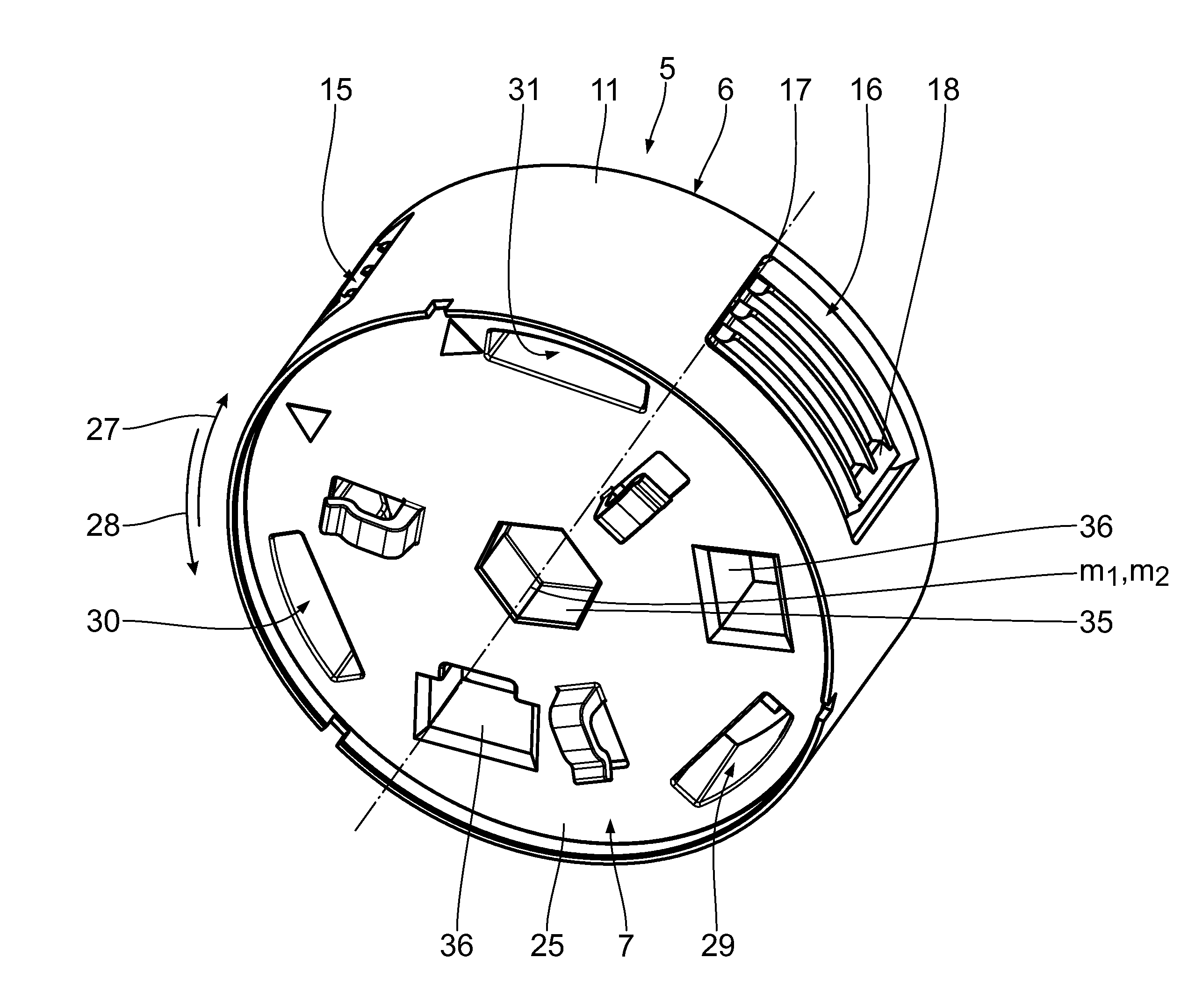
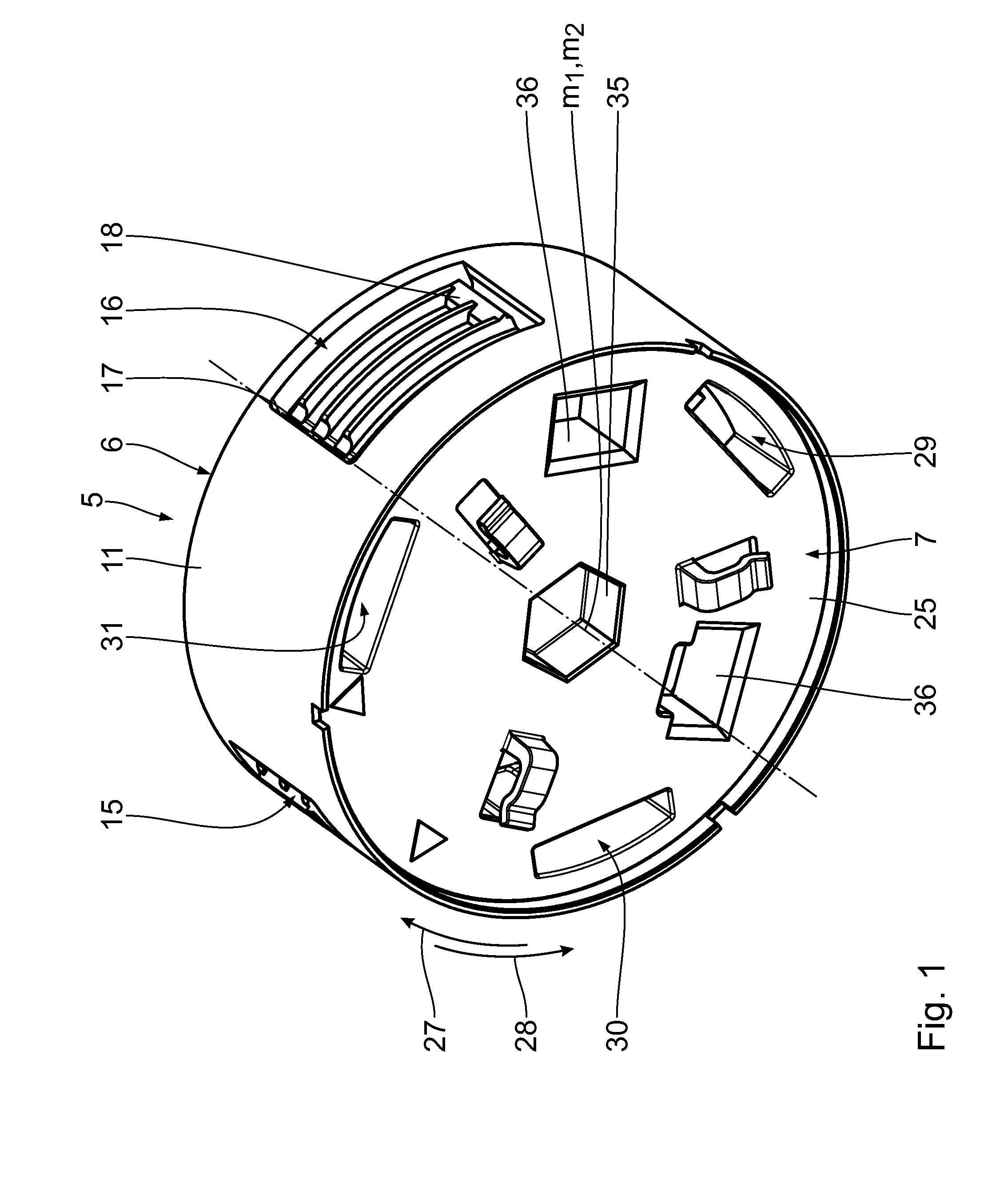
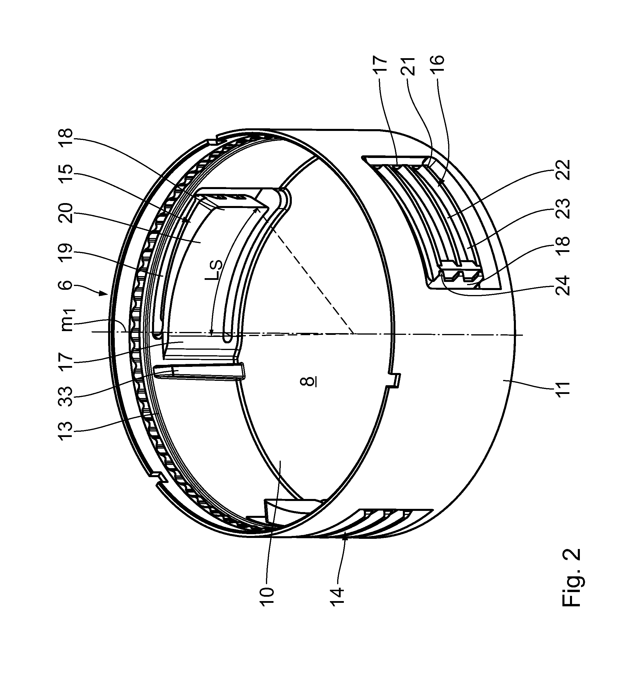
[0033]In the following sections, a first exemplary embodiment of the invention will be described with reference to FIGS. 1 to 7. An object 1 configured as a piece of furniture has a base body 2 in which a recess 3 is formed. The recess 3 has a circular cross-section and has a central longitudinal axis M, wherein a base body side wall 4 bounding the recess 3 has a distance R from said central longitudinal axis M. The recess 3 is configured as a blind hole.

[0034]The recess 3 is adapted to allow installation of an insert casing 5. The insert casing 5 includes a first casing part 6 and a second casing part 7 which define a receiving space 8. The receiving space 8 is adapted to receive an electrical or electronic component 9 which is outlined only in FIGS. 5 and 7.

[0035]The first casing part 6 has a bottom 10 with an annular side wall 11 being mounted thereto. The first casing part 6 has a central longitudinal axis m1, wherein the inner side of the side wall 11 is arranged at a distance ...


PUM

PropertyMeasurementUnit
rGaaaaaaaaaa
rGaaaaaaaaaa
outer radius RGaaaaaaaaaa

Abstract

An insert casing for receiving and fastening an electrical or electronic component includes a first casing part which is connectable to a second casing part by means of a rotary joint. The casing parts define a receiving space for the electrical or electronic component. The first casing part is provided with at least one spreading member which is spreadable by the second casing part when the rotary joint is being closed. The insert casing can be fastened easily in a recess of an object by closing the rotary joint.

Description

CROSS-REFERENCE TO RELATED APPLICATIONS[0001]This application claims the priority of Patent Application Serial No. EP 14 159 153.7 filed on 12 Mar. 2014, pursuant to 35 U.S.C. 119(a)-(d), the content of which is incorporated herein by reference in its entirety as if fully set forth herein.FIELD[0002]The device relates to an insert casing for receiving and fastening an electrical component comprising a first casing part and a second casing part connectable to the first casing part, and a receiving space defined by the casing parts for receiving an electrical component. The device further relates to an object, in particular a piece of furniture, comprising an insert casing of this type. The device further relates to a method for fastening an insert casing of this type to an object.BACKGROUND ART[0003]An insert casing for mounting an electrical device in a floor recess is known from US 2008 / 054 135 A1. The insert casing comprises a bracket having flexible retaining legs provided with b...

Claims


Application Information

Patent Timeline
Patent Type & Authority Applications(United States)
IPC IPC(8): H05K5/02H05K5/00
CPCH05K5/0217H05K5/0247H05K5/0091A47B97/00H02G3/121H02G3/185Y10T29/49876
Inventor HANTSCHEL, JORGFRANK, ROBERT
Owner WURTH ELEKTRONIK EISOS
Why Eureka
Try Eureka