Liquid Storage Container

Active Publication Date: 2015-10-01
SEIKO EPSON CORP
View PDF1 Cites 6 Cited by
  • Summary
  • Abstract
  • Description
  • Claims
  • Application Information

AI Technical Summary

Benefits of technology

[0018]It is preferable that the liquid storage container further includes a regulating section that regulates the movement of a circuit substrate on which the container-side terminal group is provided, and the regulating section is positioned farther in the direction of elasticity than the

Problems solved by technology

However, in order to save space in the container-side terminals, if the sizes of the terminals are simply reduced or intervals between the terminals are narrowed, there is a concern that contact failure with the apparatus-side terminals occurs or a failu

Method used


Image

  • Liquid Storage Container
  • Liquid Storage Container
  • Liquid Storage Container

Examples


first embodiment

Ink Cartridge

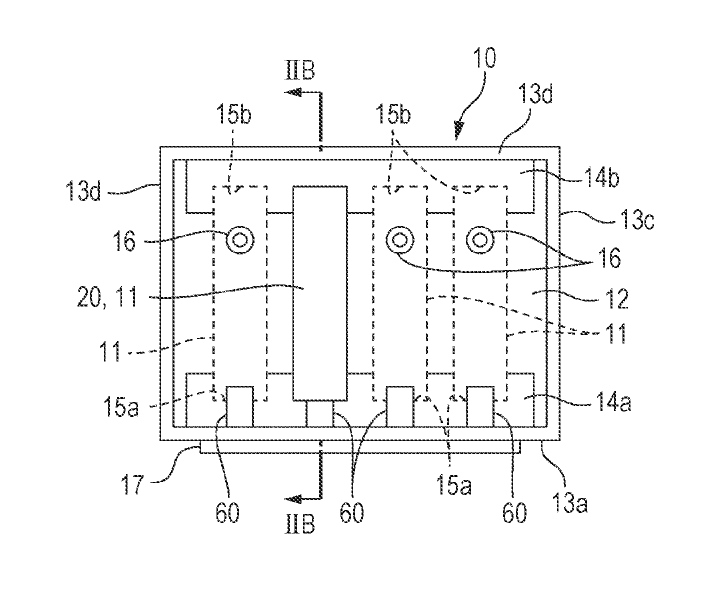
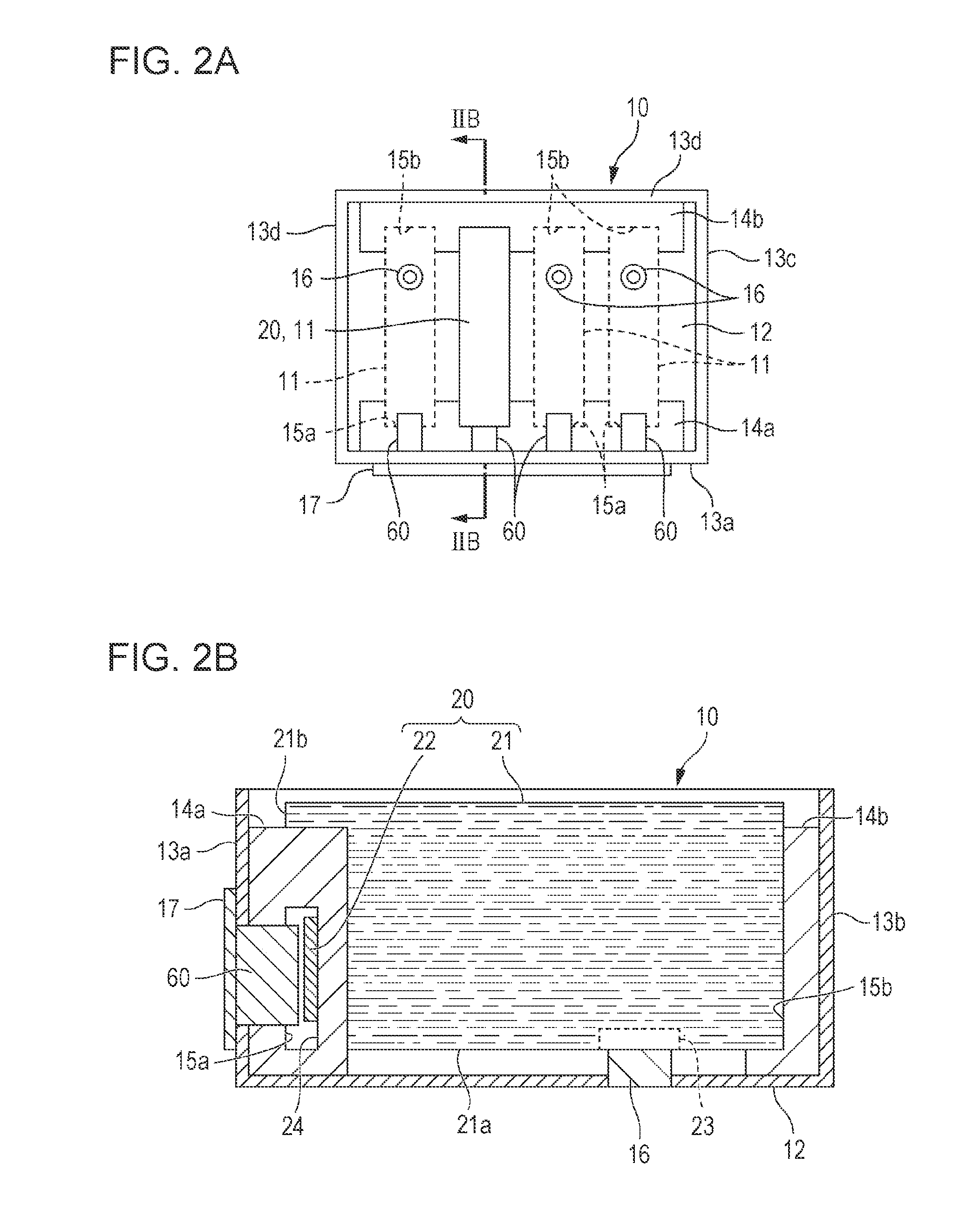
[0033]A first embodiment is a form in which a circuit substrate (container-side circuit substrate 22 described below) parallel to a mounting direction is mounted on a side surface of the ink cartridge 20. FIGS. 2A and 2B are respectively a plan view and a cross-sectional view schematically illustrating the ink cartridge 20 and the cartridge holder 10 of the first embodiment. FIG. 2A is a plan view of the cartridge holder 10 viewed from above and FIG. 2B is a cross-sectional view that is taken along line IIB-IIB of FIG. 2A. FIG. 2A illustrates a state where only one ink cartridge 20 is mounted on four cartridge mounting sections 11 provided in the cartridge holder 10. The cartridge holder 10 has a box shape and includes a rectangular bottom portion 12, a front portion 13a and a rear portion 13b standing upward from two sides facing each other of the bottom portion 12, and side portions 13c and 13d standing upward from the other two sides facing each other. Four cartridge...

second embodiment

Ink Cartridge

[0056]A second embodiment is a form in which a container-side circuit substrate 122 is mounted (inserted) on an ink cartridge 120 in an inclined posture. FIGS. 8A and 8B are cross-sectional views schematically illustrating the ink cartridge 120 and a cartridge holder 110 of the second embodiment, FIG. 8B is a partial enlarged view of a region VIIIB of FIG. 8A. Hereinafter, only a configuration different from that of first embodiment is described, the same reference numerals are given to the same configurations, and overlapping description will be omitted. In the second embodiment, a tube connecting section 16 is formed in a bottom portion 12 of the cartridge holder 110 and a terminal module 160 is disposed inside a front portion 13a of the cartridge holder 110. An apparatus-side circuit substrate 17 is mounted on the outside of the front portion 13a so as to overlap the terminal module 160. The terminal module 160 includes a housing 161 and an apparatus-side terminal 16...


PUM


Abstract

With an ink cartridge mounted on a cartridge mounting section of a printer, an apparatus-side terminal elastically comes in contact with a container-side terminal of a container-side circuit substrate. The container-side terminal includes a curved edge portion at a corner portion in which a groove of a substrate surface comes in contact with a substrate end surface. Depths of the grooves in container-side terminals are different and positions of contact sections with the apparatus-side terminals are different in the edge portions. As a result, positions in directions in which elastic forces act from the apparatus-side terminals are different for each contact section and the elastic forces having values and directions which are not uniform act on the container-side circuit substrate at different positions. Thus, it is possible to suppress positional shift of the container-side circuit substrate and to suppress contact failure between the container-side terminal and the apparatus-side terminal.

Description

CROSS-REFERENCE TO RELATED APPLICATION(S)[0001]This application claims priority to Japanese Patent Application No. 2014-075190 filed on Apr. 1 2014, the entire disclosure of which is incorporated by reference herein.BACKGROUND[0002]1. Technical Field[0003]The present invention relates to a technique in which a terminal electrically connected to a circuit substrate provided in a liquid storage container and a terminal provided in a mounting section on which the liquid storage container is mounted can be electrically connected.[0004]2. Related Art[0005]In the related art, in a printer (liquid ejecting apparatus) including a print head (liquid ejecting section) ejecting liquid such as ink, a cartridge (liquid storage container) charged with liquid is mounted on a cartridge mounting section of an apparatus body and the liquid can be supplied to the printer. A circuit substrate provided with a memory capable of recording information regarding the ink or a circuit element to which a volta...

Claims


Application Information

Patent Timeline
IPC IPC(8): B41J2/175
CPCB41J2/17526B41J2/17513
Inventor KUBOTA, TOMOO
Owner SEIKO EPSON CORP
Why Eureka
Try Eureka