Eyewear lens production by additive techniques

Active Publication Date: 2015-10-01
INDIZEN OPTICAL TECH
View PDF0 Cites 40 Cited by
  • Summary
  • Abstract
  • Description
  • Claims
  • Application Information

AI Technical Summary

Benefits of technology

[0025]In a preferred embodiment, the added material has measurably different optical or physical properties from the lens substrate. In one preferred embodiment, the added material's measurably different properties are selected from refractive index, Abbe value, abrasion resistance, impact resistance, resistance to organic solvents, resistance to bases, Tg, visible color, visible transmittance, UV transmittance, electrical conductivity, polarization, and photochromic properties.
[0026]In preferred embodiments of the invention, the radiation-polymerizable material further comprises components to tailor the optical, mechanical, chemical or physical properties o

Problems solved by technology

This can be a time-consuming process.
Digital surfacing often requires only a limited number of semi-finished lens blanks or other starting lens pieces, too, but the computer-controlled surfacing equipment allows more complex (e.g., multifocal) or individualized prescriptions to be prepared.
This method can involve significant expenses in equipment and trained personnel.
In such processes, there is often a significant amount of waste material that must be safely handled, stored and eliminated.
However, finished lenses typically only approximate prescriptions in 0.25 D increments of sphere and cylinder corrections and, therefore, may be less accurate for eyesight correction.
Even if stocked at such 0.25 D increments, the number of stocked units needed to cover the wide range of prescriptions an eyecare professional will need is huge.
These downfalls counteract the processing advantages that may be realized with finished lenses.
Often these supports are flat platforms, which are not intrinsical

Method used


Image

  • Eyewear lens production by additive techniques
  • Eyewear lens production by additive techniques
  • Eyewear lens production by additive techniques

Examples


example 1

[0145]As illustrated in FIG. 6, a lens substrate 11 is mounted on lens substrate support 70 that allows controlled, fixed positioning of the lens substrate. In this Example, lens substrate support 70 comprises multiple points that contact, support and fixedly position the lens substrate. The convex surface of the lens substrate is further protected by a protective element 90, and support 70 contacts the protective element 90 while supporting the substrate.

[0146]The lens substrate 11 is a finished plano comprising finished and polished concave and convex surfaces. The lens substrate is made from a lens material with a refractive index of 1.5, with radii of curvature on both its convex and concave surfaces of 125 mm, and a minimum thickness of 1.0 mm. The lens substrate has a rectangular shape that is 50 mm wide (along the horizontal axis of the lens as it will be mounted in the frame and worn) and 30 mm in height. The concave surface will be exposed to the flowable radiation-polymeri...

example 2

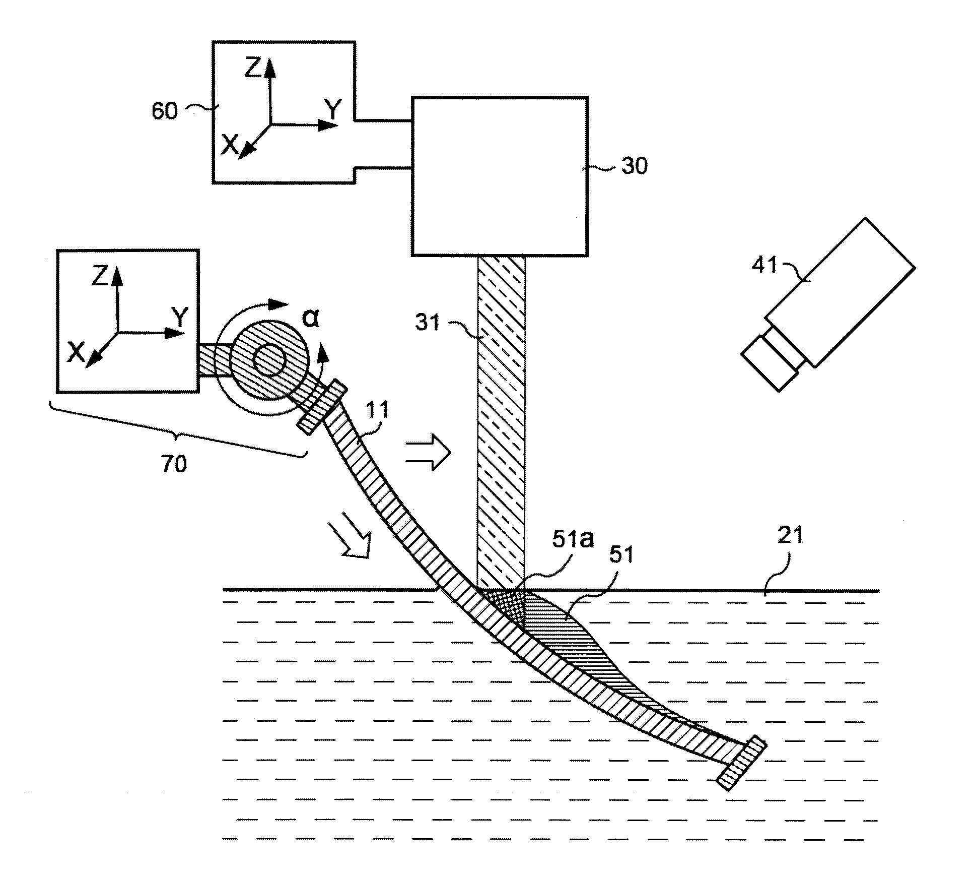
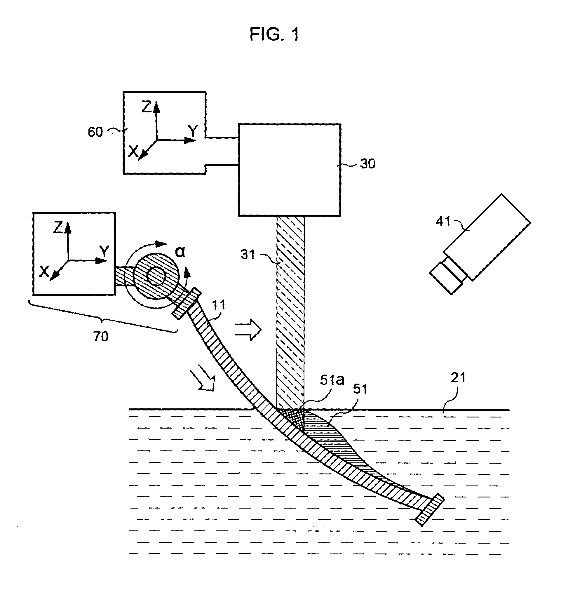
[0157]In another embodiment, a −2 D 65 mm round hard resin (n=1.50) lens substrate 11 is mounted in a configuration as illustrated in FIG. 1. In this Example, material is intended to be polymerized onto the concave (uppermost as viewed in FIG. 1) surface of the lens substrate to create a +2.00 D add power in an 25 mm round area on the lower portion of the inner surface of the resultant lens as it will be worn in an eyeglass frame. This 25 mm area corresponds to a region near the edge of the lower right-hand portion of the uppermost lens surface in FIG. 1.

[0158]A 365 nm mercury atomic emission lamp with collimating optics is used for irradiating beam 31 to provide a 5 mm circular diameter irradiating beam. A CCD camera 41 is used to view the surface of the lens substrate, the flowable radiation-polymerizable material and the added material on the lens substrate created by the process. The flowable radiation-polymerizable material will provide added polymerized material with a refract...


PUM

PropertyMeasurementUnit
Angleaaaaaaaaaa
Electrical conductivityaaaaaaaaaa
Coloraaaaaaaaaa

Abstract

A method that adds material selectively to a lens substrate and is used to produce a customized eyewear lens with optical power that is discernibly different from the optical power of the lens substrate. The method involves obtaining the lens substrate, calculating and generating an added material design to convert the lens substrate's optical power to a desired optical power for the customized eyewear lens, contacting the lens substrate with a bulk source of flowable radiation-polymerizable material, and irradiating the material with radiation that is controlled for wavelength range, energy and spatial distribution to polymerize the radiation-polymerizable material only in a selected area according to the added material design. The method does not require the use of external shaping structures to form the customized lens on the lens substrate, and the added material is integrally bonded to the substrate.

Description

CROSS-REFERENCE TO RELATED APPLICATIONS[0001]This application is a continuation-in-part of application Ser. No. 14 / 226,686, filed Mar. 26, 2014.FEDERALLY SPONSORED RESEARCH OR DEVELOPMENT[0002]Not applicable.JOINT RESEARCH AGREEMENT[0003]Not applicable.SEQUENCE LISTING[0004]Not applicable.BACKGROUND OF THE INVENTION[0005]1. Field of the Invention[0006]The field of the invention relates generally to methods of producing eyewear lenses, particularly finished lenses and lens blanks using additive techniques rather than removal of excess material.[0007]2. Description of Related Art[0008]Prescription eyewear lenses are commonly used to correct human vision errors, aberrations and focusing deficiencies caused by genetics, age, disease or other factors. In addition to correcting physiological vision problems, eyewear lenses may be used as a fashion accessory or to protect the eyes from hazards or discomfort.[0009]Prescription eyewear lenses must be prepared to meet each individual's specif...

Claims


Application Information

Patent Timeline
IPC IPC(8): G02C7/02B29D11/00B29C67/00
CPCG02C7/027B29C67/0066B29D11/00009B33Y50/02B33Y10/00B33Y80/00B29D11/00951B29D11/00442B29C64/135G02C7/022B29C64/268
Inventor CRESPO VAZQUEZ, DANIELFERNANDEZ, JOSE ALONSOQUIROGA, JUAN ANTONIOMCKENZIE, ANDREW JOHNAMBLER, DAVID MARK
Owner INDIZEN OPTICAL TECH
Why Eureka
Try Eureka