Forage harvesting machine with an improved deflector

a deflector and forage technology, applied in the field of forage harvesting haymaking machines, can solve the problems of reducing the risk of one or the other of these elements being damaged to the point insufficient deflector movement from its initial operation position, and reducing mechanical stresses on the deflector and its connecting device, so as to achieve the effect of greatly reducing the risk of hindering correct operation, reducing the risk of one or the other of these elements being damaged to the point o

Inactive Publication Date: 2015-10-08
KUHN SA
View PDF14 Cites 13 Cited by
  • Summary
  • Abstract
  • Description
  • Claims
  • Application Information

AI Technical Summary

Benefits of technology

The invention is a connecting device for a work unit and a deflector that allows the deflector to move in a direction opposite to the movement of the machine when a force exerted on the deflector exceeds a threshold. This feature helps to dissipate energy from the impact between the deflector and an obstacle, reducing mechanical stresses and damage to the deflector and its connecting device. The connecting device also allows the deflector to move longitudinally in a direction opposite to the movement of the machine when a force exerted on the deflector exceeds a second threshold, increasing protection against impact from obstacles at the rear of the deflector. The deflector can also be lifted from the ground, reducing damage and mechanical stresses.

Problems solved by technology

This longitudinal movement of the deflector in the direction opposite the movement direction of the machine results in dissipating part of the energy from the impact between the deflector and the obstacle.
The risk of one or the other of these elements being damaged to the point of hindering correct operation is greatly decreased.
The resultant of the forces exerted by the plants shifted sideways by the work unit and colliding with the deflector, and the forces exerted by the rubbing of the deflector on the ground and / or with short plants present on the ground, is then insufficient for the deflector to move from its initial operation position.

Method used


Image

  • Forage harvesting machine with an improved deflector
  • Forage harvesting machine with an improved deflector
  • Forage harvesting machine with an improved deflector

Examples


Embodiment Construction

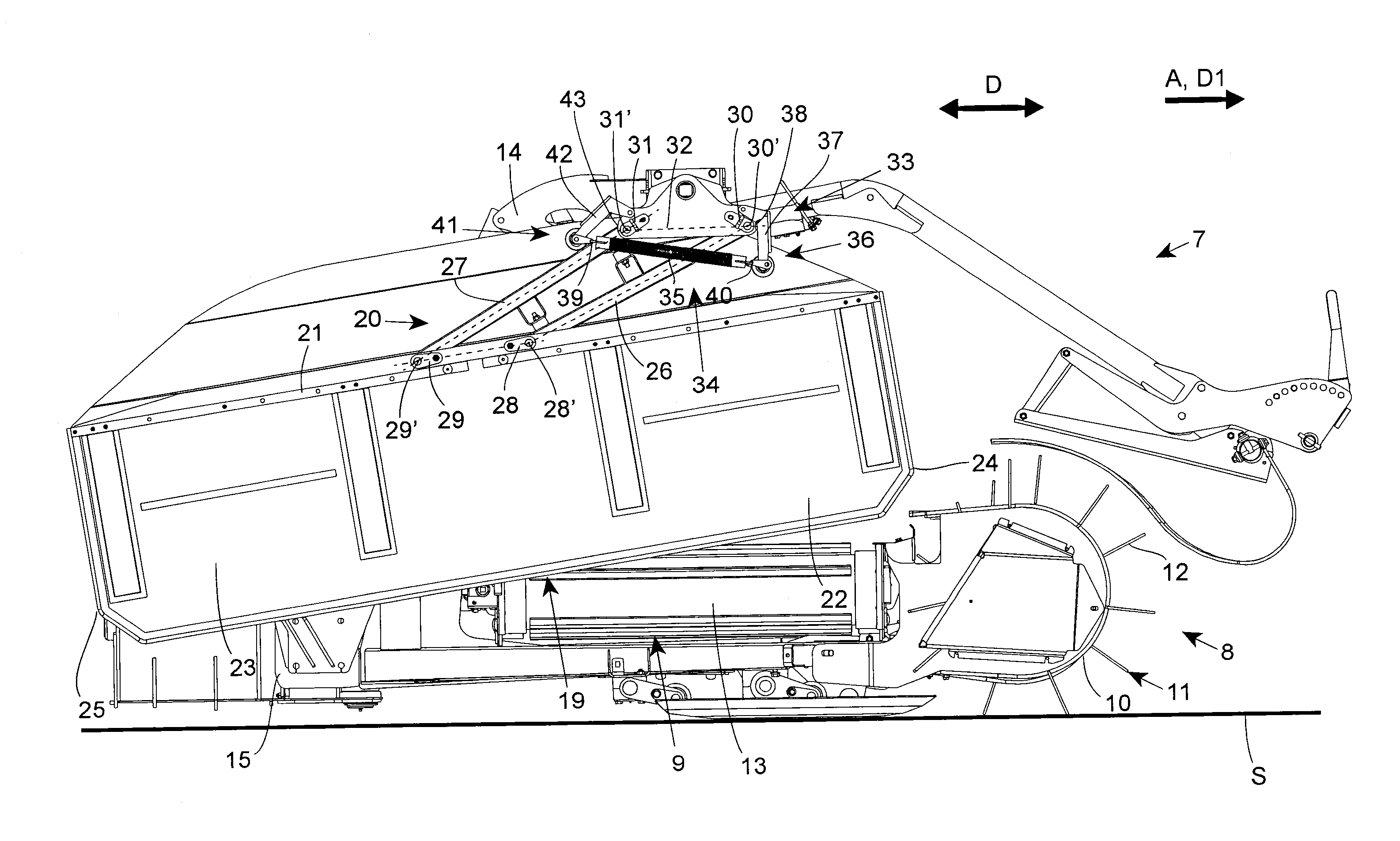
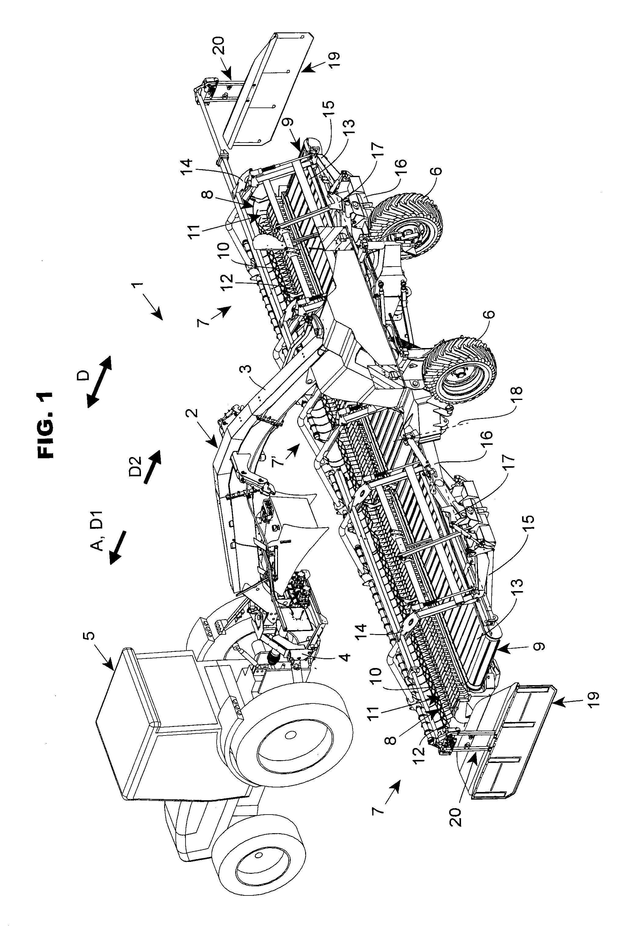
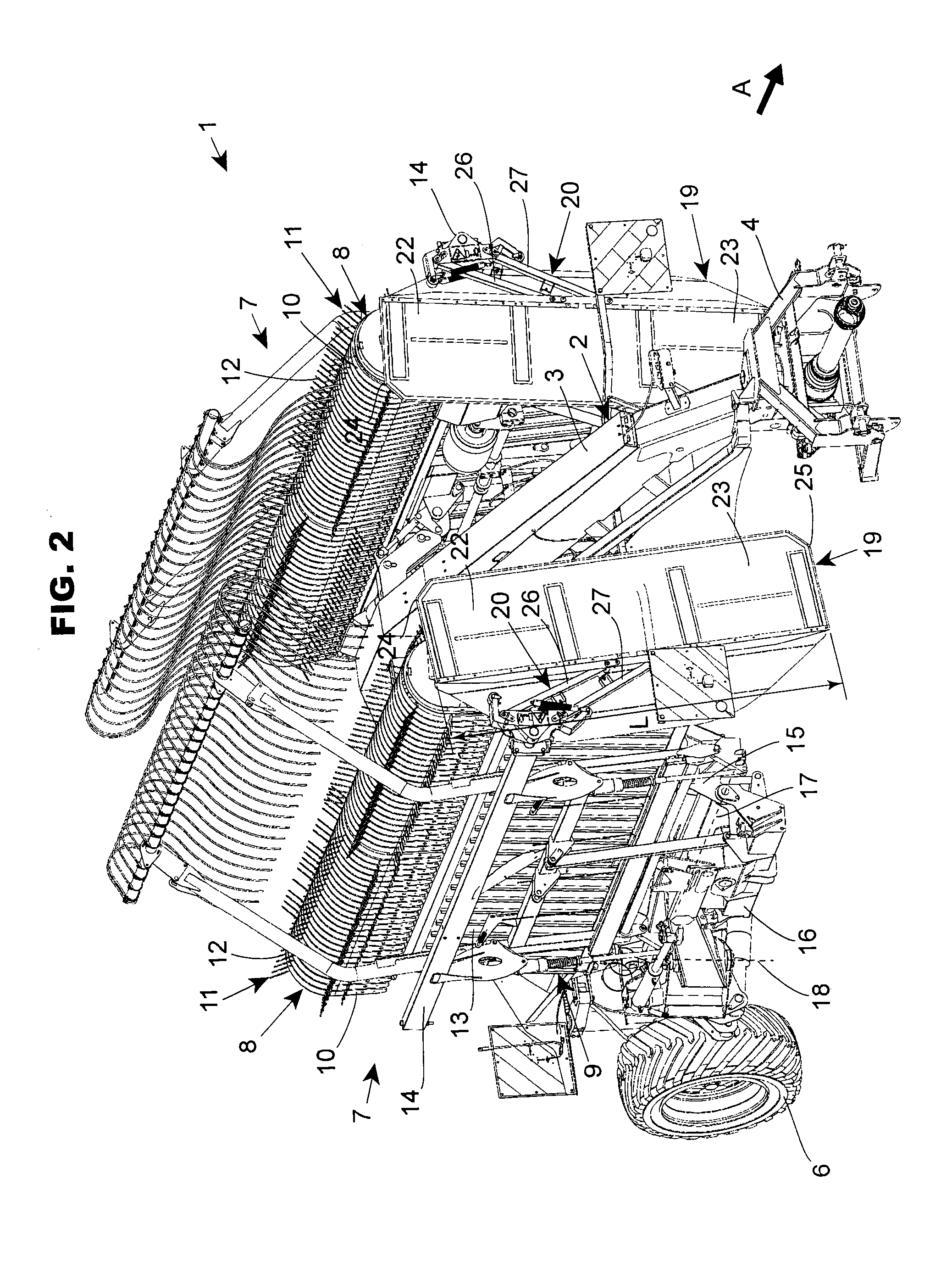
[0017]The machine 1 according to the invention is an agricultural machine for forage harvesting, in particular a haymaking machine for forage windrowing. Such a machine 1 is in particular a windrower for plants lying on the ground. The machine 1 comprises a frame 2. In the example embodiment illustrated in FIG. 1, this frame 2 comprises a more or less central longitudinal beam 3. The frame 2 further comprises a hitching device 4, which is placed at the front end of said longitudinal beam 3. The hitching device 4 makes it possible to connect the frame 2 to a motor vehicle, for example a tractor 5, in order to move the machine in a direction of advance A. In the following description, the terms “left”, “right”, “front”, “back” and “rear” refer to the direction of advance A, and the terms “upper”, “high”, “top” and “bottom” are defined relative to the ground S. A power take-off of the motor vehicle drives the various work elements of the machine 1. The frame 2 is supported on the groun...


PUM


Abstract

An agricultural machine for forage harvesting, including a frame supporting a work unit able to occupy a work position in which it can pick up plants lying on the ground and shift them sideways, a side deflector being connected to the frame by a connecting device allowing the deflector to occupy an operation position relative to the work unit, in which the deflector can receive a flow of plants shifted sideways by the work unit. The connecting device is designed so that, while the machine moves in a direction and the work unit is in the work position, the deflector can perform a movement relative to the work unit from the operation position, longitudinally in a direction opposite the movement direction, when a resultant of a force exerted on the deflector exceeds a determined threshold.

Description

BACKGROUND OF THE INVENTION[0001]1. Field of the Invention[0002]The present invention relates to an agricultural machine for forage harvesting, in particular a hay-making machine for forage windrowing, comprising a frame supporting at least one work unit able to occupy a work position in which the work unit can pick up plants lying on the ground and shift them sideways, a side deflector being connected to the frame by means of a connecting device allowing the deflector to occupy an operation position relative to the work unit, in which the deflector cooperates with the work unit so as to receive a flow of plants shifted sideways by the work unit to form a windrow.[0003]2. Discussion of the Background[0004]A machine of this type is known from application FR 1 350 393, filed by the applicant. In this machine, the operation position of the deflector is that in which the latter is situated beside the corresponding work unit and can then, during the work of the machine, receive a flow of...

Claims


Application Information

Patent Timeline
Patent Type & Authority Applications(United States)
IPC IPC(8): A01D57/28
CPCA01D57/28A01D78/1071A01D78/1085
Inventor GANTZER, CHRISTIANDIEBOLD, BERTRAND
Owner KUHN SA
Why Eureka
Try Eureka