Turbomachine comprising a device for the cooling of a pylon

a technology for turbomachines and cooling devices, which is applied in the direction of machines/engines, efficient propulsion technologies, transportation and packaging, etc., can solve the problems of mechanical strength, negative impact on the performance of turbomachines, and the life of pylons, so as to maximize the effectiveness of the cooler device and minimize the size

Active Publication Date: 2015-10-08
SN DETUDE & DE CONSTR DE MOTEURS DAVIATION S N E C M A
View PDF24 Cites 8 Cited by
  • Summary
  • Abstract
  • Description
  • Claims
  • Application Information

AI Technical Summary

Benefits of technology

[0036]It may be assumed that two ducts are arranged on either side of the pylon when seen in radial section of the turbomachine, each duct being arranged on a respective...

Problems solved by technology

In such a turbomachine, the hot gas from the nozzle heats the pylon, thereby leading to problems of mechanical strength and to problems of lifetime fo...

Method used


Image

  • Turbomachine comprising a device for the cooling of a pylon
  • Turbomachine comprising a device for the cooling of a pylon
  • Turbomachine comprising a device for the cooling of a pylon

Examples


Embodiment Construction

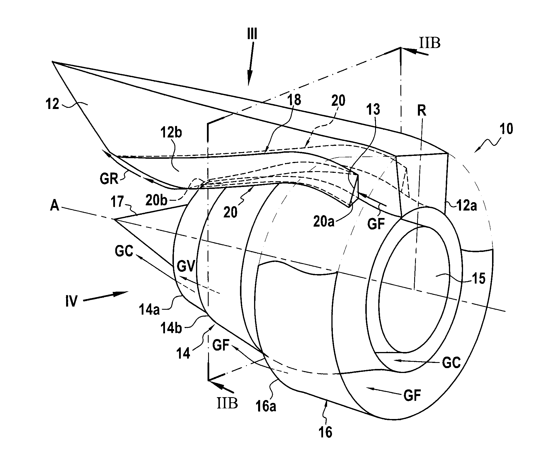
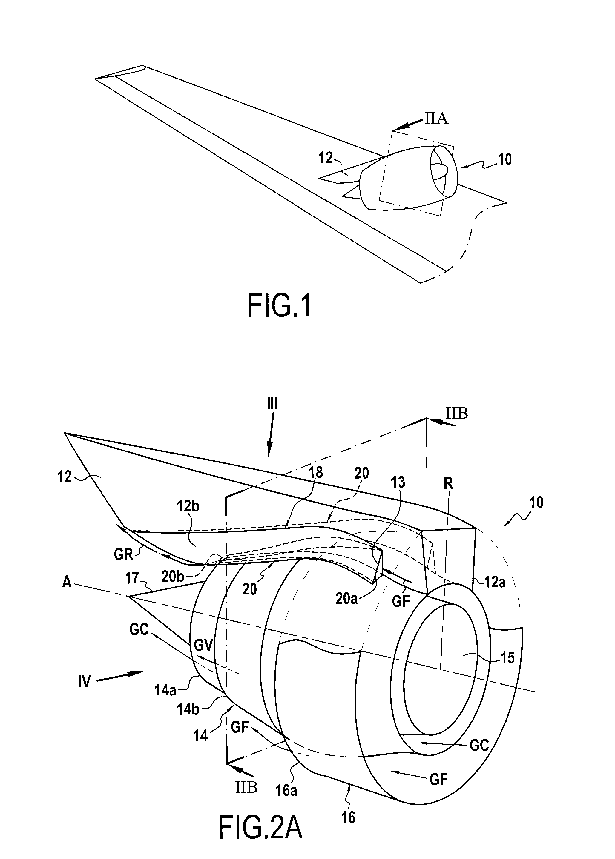
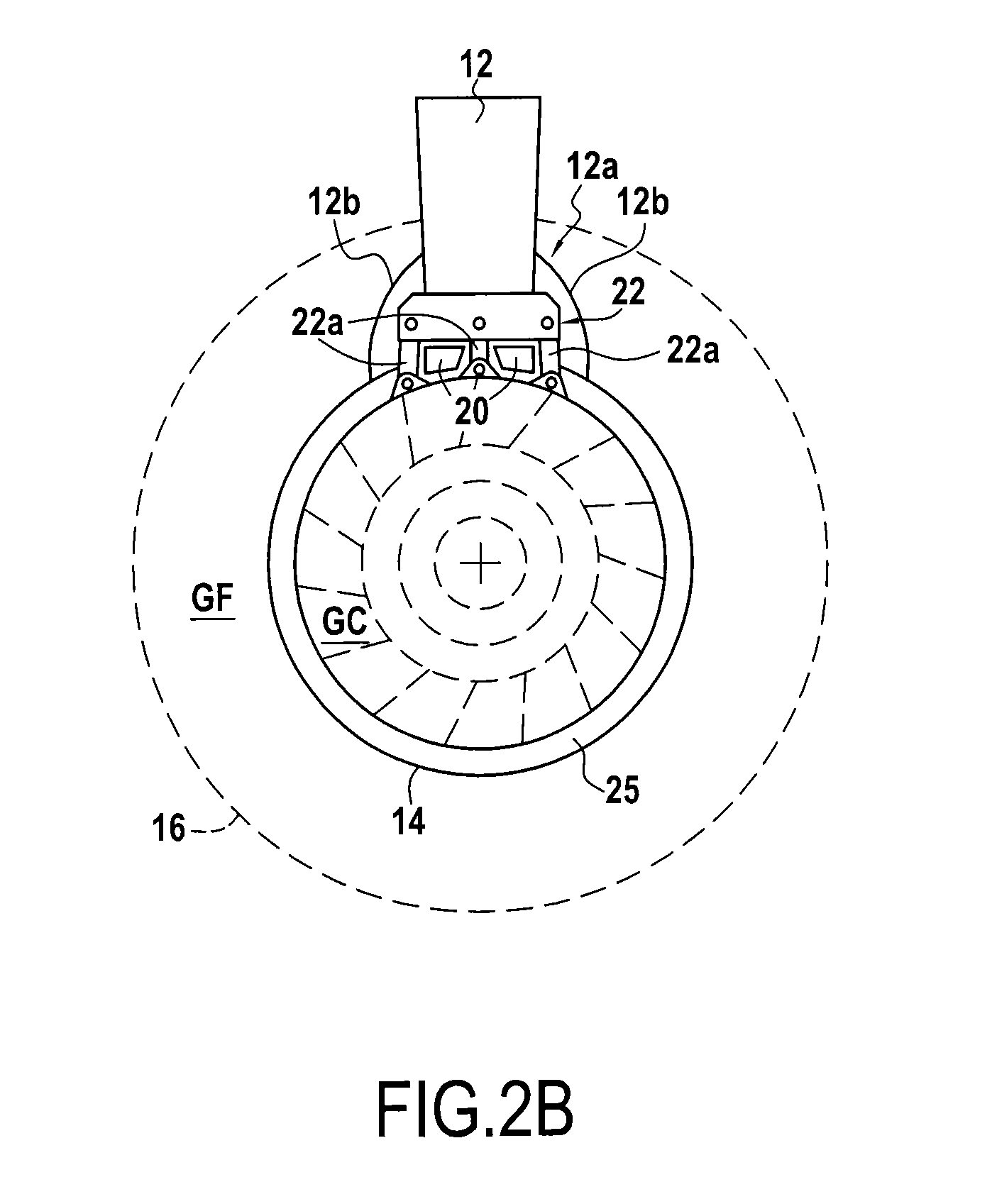
[0044]FIG. 1 shows a turbomachine, in this example a turbojet 10, having a pylon 12 and fastened by the pylon 12 to an airplane wing. The turbojet 10 is described in greater detail with reference to FIGS. 2, 3, and 4.

[0045]FIG. 2 shows the turbojet 10 in perspective and in section on plane IIA of FIG. 1. The turbojet 10 comprises a nozzle 14 (or first nozzle 14) extending along an axial direction A corresponding to the axis of rotation of the turbine 15. The turbojet also has a second nozzle 16 for the secondary stream and presenting an outlet 16a. The second nozzle 16 is coaxial with the first nozzle 14, being outside the first nozzle 14. The turbojet 10 is a bypass turbojet in which the first nozzle 14 conveys a hot gas stream GC (or primary stream of hot gas) while the second nozzle 16 conveys a cold gas stream GF (or secondary stream of cold gas). More particularly, the hot gas stream GC flows inside the first nozzle 14, while the cold gas stream GF flows between the first nozzl...


PUM


Abstract

A turbomachine (10) comprising a nozzle (14) extending along an axial direction (A), said nozzle (14) being configured to convey a hot gas stream (GC), and a mounting pylon (12) for mounting the turbomachine, said pylon (12) extending radially from a base (12a) arranged in the vicinity of the nozzle (14). The turbomachine (10) includes a pylon cooler device (18) having at least one auxiliary gas duct (20) having a gas inlet (20a) configured to take cold gas (GF) from the outside of the nozzle (14), and a gas outlet (20b) opening out in the vicinity of the base (12a) of the pylon (12).

Description

FIELD OF THE INVENTION[0001]The present invention relates to a turbomachine cooler device, and more particularly to a device for cooling a mounting pylon of a turbomachine.[0002]The term “turbomachine” designates any gas turbine apparatus producing drive, including in particular turbojets that deliver thrust needed for jet propulsion by ejecting hot gas at high speed, and turboshaft engines in which the drive is delivered by rotating a drive shaft. For example, turboshaft engines are used as engines for helicopters, ships, trains, or indeed for industrial plants. Turboprops (turboshaft engines driving propellers) are also turboshaft engines used as aeroengines.STATE OF THE PRIOR ART[0003]A turbomachine is known that has a nozzle extending along an axial direction, said nozzle being configured to convey a hot gas stream, and a mounting pylon via which the turbomachine is mounted, said pylon extending radially from a base that is arranged in the vicinity of the nozzle.[0004]In such a ...

Claims


Application Information

Patent Timeline
IPC IPC(8): B64D13/00B64D33/04B64D27/12B64D27/26
CPCB64D13/006B64D27/12B64D33/04B64D27/26B64D29/00F02K1/822F02C7/20F05D2260/20F05D2260/231B64D33/08B64C7/02Y02T50/60
Inventor LEYKO, MATTHIEUBERTUCCHI, JEANSZYDLOWSKI, JULIEN
Owner SN DETUDE & DE CONSTR DE MOTEURS DAVIATION S N E C M A
Why Eureka
Try Eureka