Vacuum powered lifting mechanism

a technology of lifting mechanism and vacuum pump, which is applied in the direction of suspension devices, machine supports, applications, etc., can solve the problems of constant use of electricity to provide power, high maintenance costs of aircraft, and safety concerns

Active Publication Date: 2015-10-08
BE AEROSPACE INCORPORATED
View PDF4 Cites 11 Cited by
  • Summary
  • Abstract
  • Description
  • Claims
  • Application Information

AI Technical Summary

Benefits of technology

[0007]Briefly, and in general terms, the present invention provides for a vacuum powered system for moving a movable component movable in opposing first and second directions between first and second positions relative to a fixed structure. The vacuum powered system can be used with aircraft overhead stowage bins or other types of stowage containers or devices, for articulation of aircraft seats, leg rests and the like, deploying an expandable compartment such as a crew rest or lavatory, retrieving galley carts or standard units from a rear of a galley, compacting trash, deploying overhead video monitors, opening and closing doors and other panels, variable comfort control of mattresses and other cushions, reconfiguring seating in a cabin, and the like. The vacuum powered system utilizes a vacuum powered lifting system or lift assist mechanism that can be retrofitted in existing aircraft, and utilizes vacuum actuation for lifting, requiring a minimum draw of electrical power.

Problems solved by technology

However, typically such systems use an electric motor, which can be disadvantageous.
For example, in the case of electrical failure or reduced electrical power, a passenger or flight attendant may be trapped in a lavatory or injured by a lowered stowage bin, causing safety concerns.
Furthermore, constant use of electricity to provide power to every motorized feature in an aircraft, from lowering stowage bins and opening lavatory doors to deploying video monitors and compacting trash, added on top of cabin pressure monitoring and other control systems, can be expensive for an aircraft to maintain.

Method used


Image

  • Vacuum powered lifting mechanism
  • Vacuum powered lifting mechanism
  • Vacuum powered lifting mechanism

Examples


Embodiment Construction

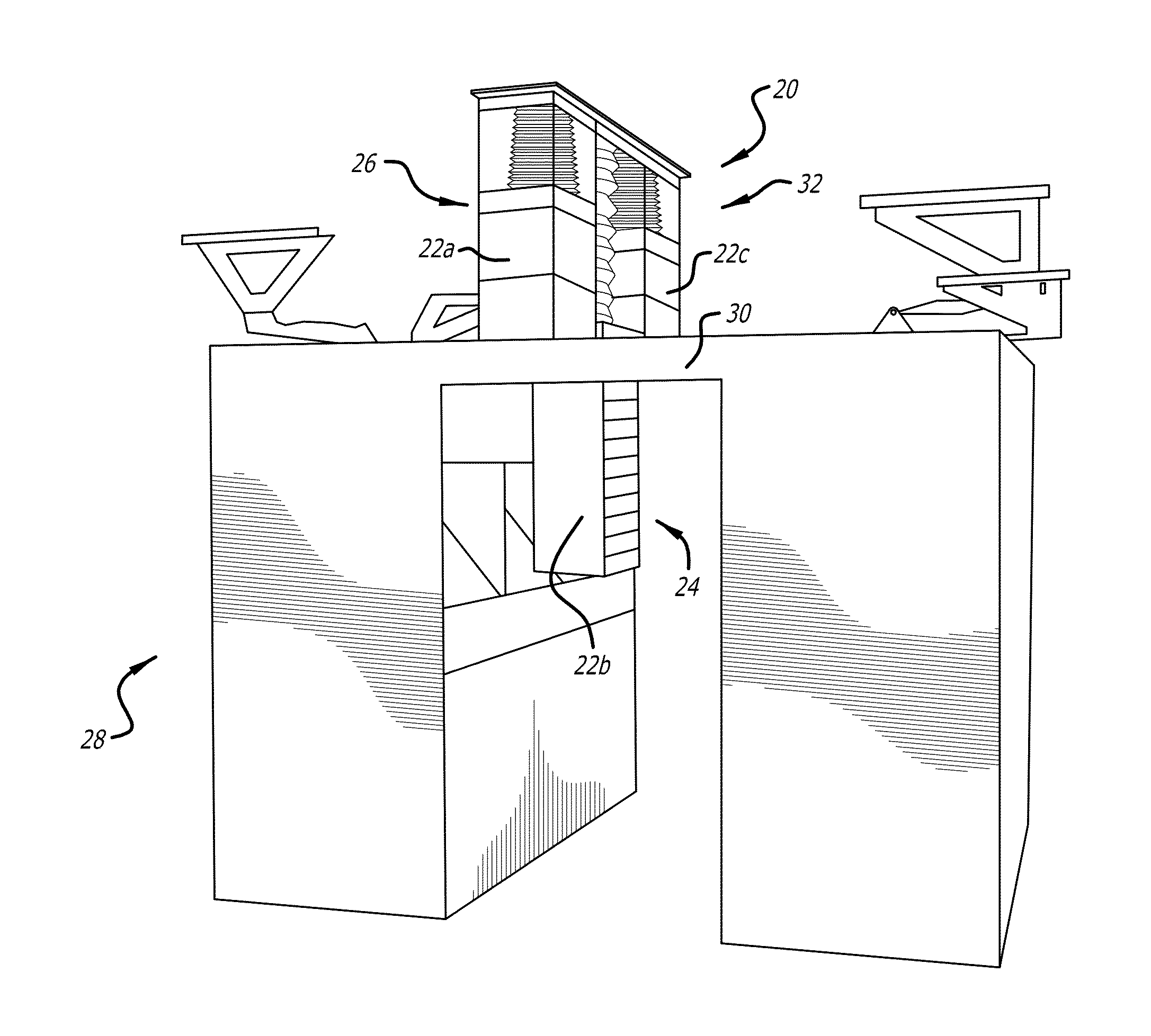
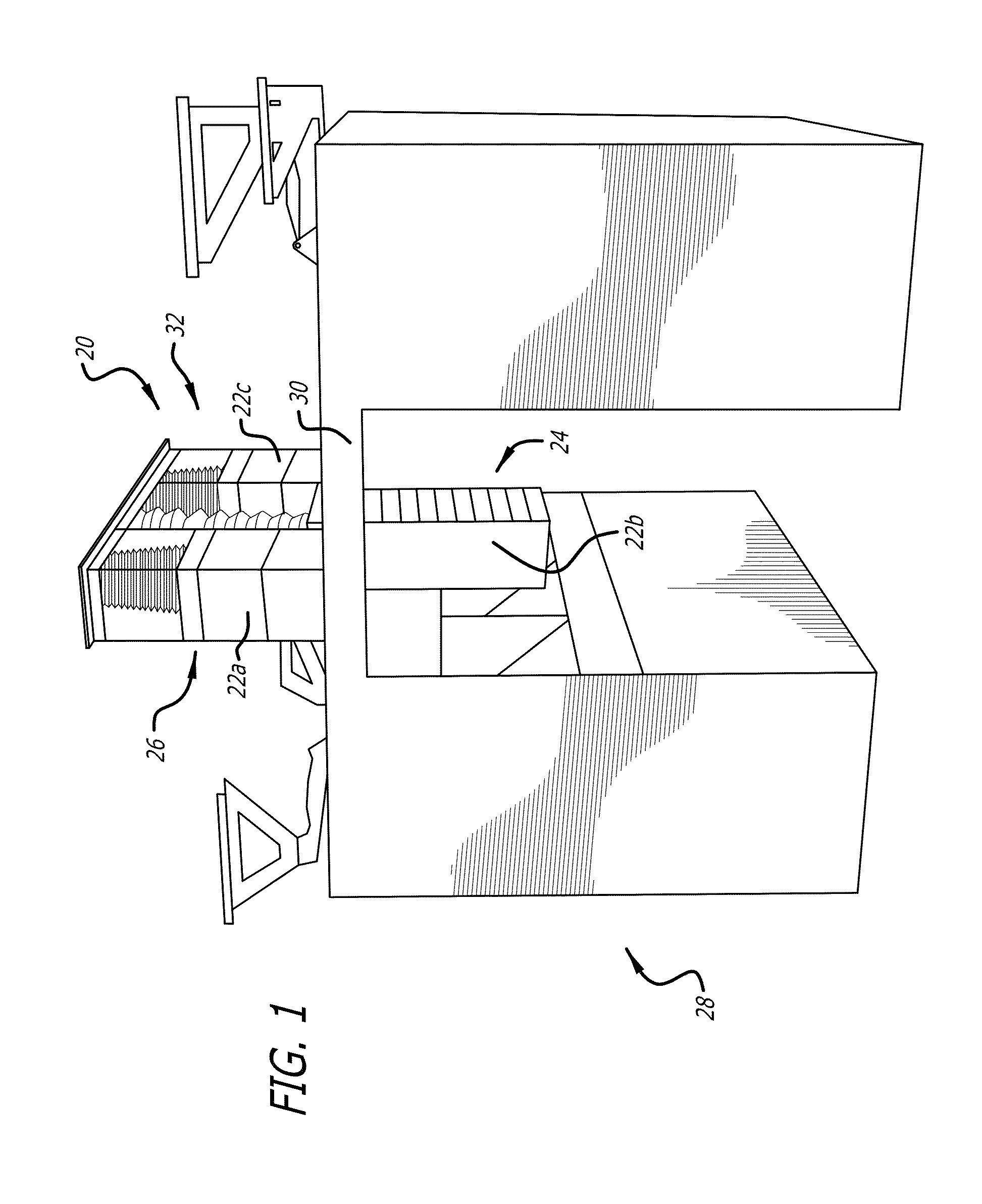
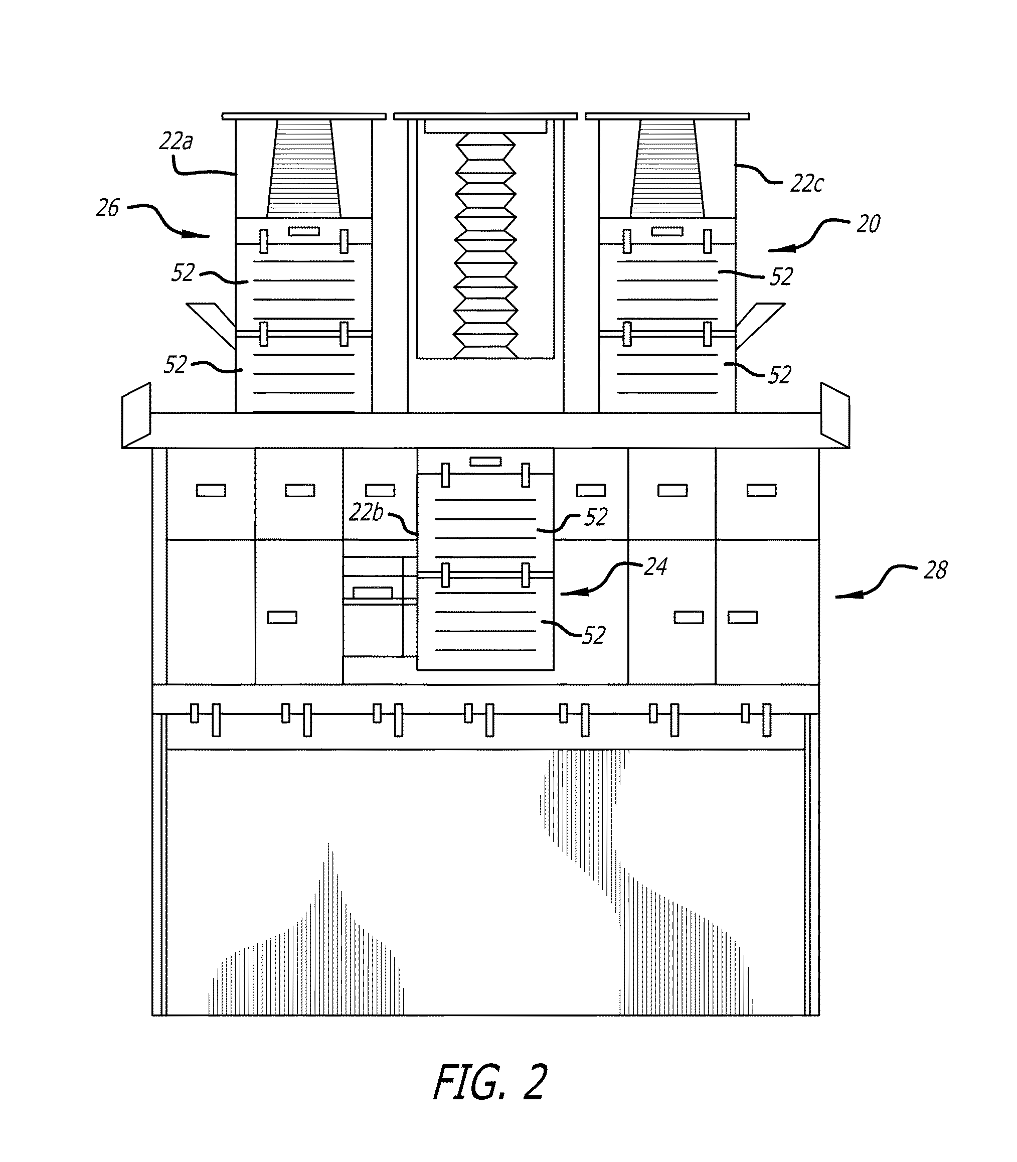
[0031]Referring to the drawings, which are provided by way of illustration and example, and not by way of limitation, the present invention provides for a vacuum powered system 20 for moving or lifting one or more movable components, for example stowage containers 22a, 22b, and 22c, between a first position and a second position. As shown in FIGS. 1-7, the vacuum powered system provides a lifting force for moving stowage containers in an aircraft between a lowered or deployed position 24 for accessing the stowage container for loading and unloading items, and a raised or stowed position 26 for storing the stowage container.

[0032]Referring to FIGS. 1 and 2, according to a presently preferred aspect, the vacuum powered system is implemented in a full service aircraft galley 28, which typically includes a beverage center, one or more oven and / or chiller units, one or more galley cart bays, and the like. Aircraft galley typically includes a ceiling panel 30, with storage space 32 above ...


PUM


Abstract

A vacuum powered system for moving a movable component, such as for raising and lowering a stowage container, includes a vacuum actuator connected between a fixed structure and a movable component. The vacuum actuator includes one or more intake ports that are configured to connect with a source of vacuum for moving the movable component in a first direction to a first position, and one or more bleed valve ports for venting the vacuum actuator to move the movable component in a second direction to a second position. The vacuum actuator may be an air bellows, a single acting linear vacuum actuator, or a dual acting linear vacuum actuator. A guiding system is further provided that includes elongated tracks in a stationary stowage container housing that houses the movable component, and corresponding guide elements on the movable component that slidably engage with the elongated tracks for moving the movable component.

Description

CROSS-REFERENCES TO RELATED APPLICATIONS[0001]This application claims priority from U.S. Application No. 61 / 974,095, filed Apr. 2, 2014, incorporated by reference in its entirety.BACKGROUND[0002]The present invention relates generally to lift assist mechanisms, and more particularly to vacuum powered lifting systems for moving a movable component such as an aircraft stowage bin or container.[0003]Pivoting aircraft overhead stowage bins or containers typically rely on force provided by an operator, such as a passenger or flight attendant, for example, to close and secure the stowage container, and typically have no operator assist. Springs or other simple mechanisms designed to assist in moving stowage containers or devices generally force users to pull downward on the container or device for loading when it is empty or only lightly loaded, and to push upward on the container or device when it is fully loaded.[0004]Power-assisted stowage bin systems have been used as an attempt to so...

Claims


Application Information

Patent Timeline
Patent Type & Authority Applications(United States)
IPC IPC(8): F15B15/14B64D11/00F16M13/02
CPCF15B15/149B64D11/00F16M13/022B64D11/003F15B15/10F16J3/06F15B2211/411F15B2211/41581F15B2211/89F15B2211/7052F15B2211/7053B64D11/04
Inventor CLAFLIN, SHAWN A.HAUSER, JAMES B.
Owner BE AEROSPACE INCORPORATED
Why Eureka
Try Eureka