

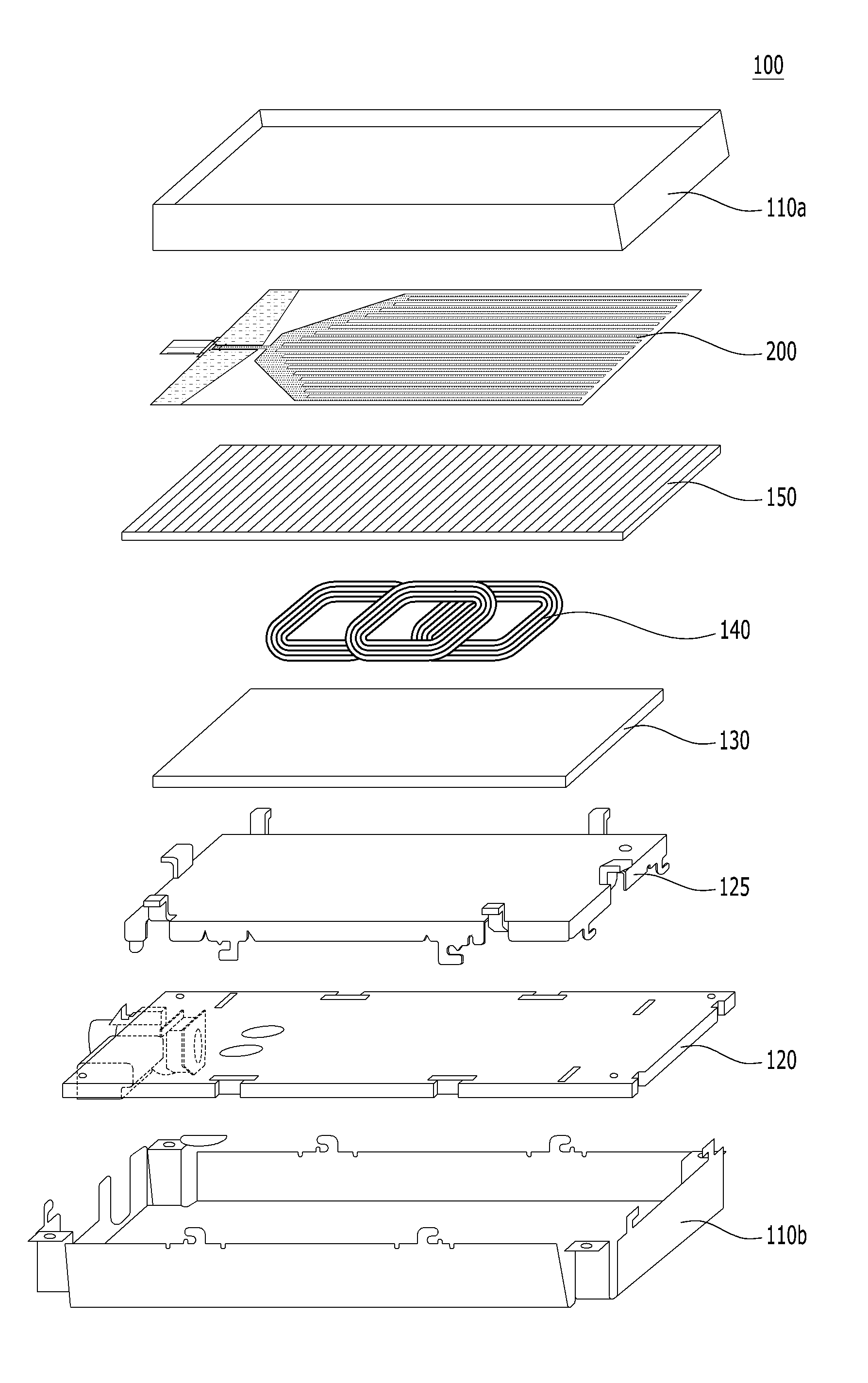
Reradiation antenna and wireless charger
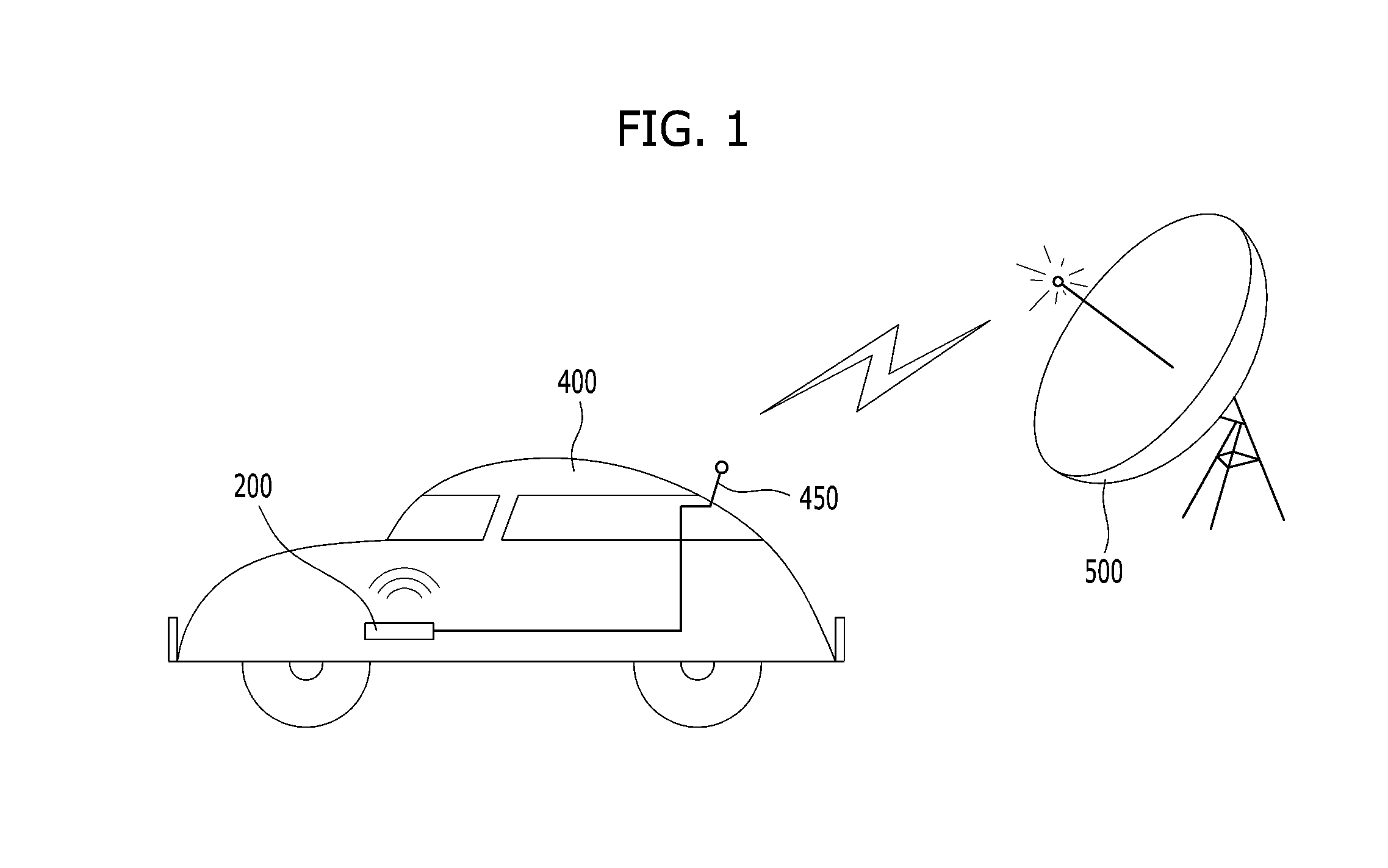
a technology of reradiation antenna and wireless charger, which is applied in the direction of substantially flat resonant elements, resonance antennas, transportation and packaging, etc., can solve the problems of poor propagation environment, degraded transmission and reception rate of radio waves, and influence of technology on surrounding electronic devices, so as to improve the communication environment and not degrade the performance of wireless chargers.
- Summary
- Abstract
- Description
- Claims
- Application Information
AI Technical Summary
Benefits of technology
Problems solved by technology
Method used
Image

Examples
Embodiment Construction
[0037]Description will now be given in detail according to embodiments disclosed herein, with reference to the accompanying drawings. For the sake of brief description with reference to the drawings, the same or equivalent components may be provided with the same reference numbers, and description thereof will not be repeated. In general, a suffix such as “module” and “unit” may be used to refer to elements or components. Use of such a suffix herein is merely intended to facilitate description of the specification, and the suffix itself is not intended to give any special meaning or function.
[0038]The accompanying drawings are used to help easily understand various technical features and the embodiments presented herein are not limited by the accompanying drawings. As such, the present invention should be construed to extend to any alterations, equivalents and substitutes in addition to those which are particularly set out in the accompanying drawings. Although the terms first, seco...
PUM
 Abstract
Description
Claims
Application Information