System and Method for Compressing Video and Reformatting the Compressed Video to Simulate Uncompressed Video With a Lower Bandwidth

a compression system and compression technology, applied in the field of video compression, can solve the problems of large cabling, large installation cost, and limitations of transmission and switching technologies, and render such equipment or cabling obsolete,

Active Publication Date: 2015-10-08
CRESTRON ELECTRONICS
View PDF13 Cites 42 Cited by
  • Summary
  • Abstract
  • Description
  • Claims
  • Application Information

AI Technical Summary

Benefits of technology

[0021]According to still another aspect, the invention involves a method of determining the bandwidth limitation of a video distribution system that comprises a transmitter, a receiver, and one or more displays. The method includes reading the EDID of each of the one or more displays, determining, from each display EDID, the bandwidths supported by each of the one or more displays, determining the highest common bandwidth for all of the one or more displays, reading the EDID of at least each of the transmitter and the receiver, determining, from the EDID of at least each of the transmitter and the receiver, the bandwidths supported by the transmitter and the receiver, determining the highest common bandwidth for at least the transmitter and the receiver, comparing the highest common bandwidth for all of the one or more displays to the highest common bandwidth for at least the transmitter and the receiver, and determining the bandwidth limitation of the video distribution system based on the comparison.

Problems solved by technology

The cost of an installation that includes a large matrix switcher, interface boxes that extend the signal transmission distance, and cabling can be large.
All of the above-described transmission and switching technologies have limitations.
Inevitably, new video formats / interfaces are introduced that exceed the capabilities of existing equipment or cabling, thus rendering such equipment or cabling obsolete.

Method used


Image

  • System and Method for Compressing Video and Reformatting the Compressed Video to Simulate Uncompressed Video With a Lower Bandwidth
  • System and Method for Compressing Video and Reformatting the Compressed Video to Simulate Uncompressed Video With a Lower Bandwidth
  • System and Method for Compressing Video and Reformatting the Compressed Video to Simulate Uncompressed Video With a Lower Bandwidth

Examples


Embodiment Construction

[0138]Reference will now be made to the exemplary embodiments illustrated in the drawings, and specific language will be used herein to describe the same. It will nevertheless be understood that no limitation of the scope of the invention is thereby intended. Alterations and further modifications of the inventive features illustrated herein, and additional applications of the principles of the inventions as illustrated herein, which would occur to one skilled in the relevant art and having possession of this disclosure, are to be considered within the scope of the invention.

[0139]Unless the context clearly requires otherwise, throughout the description and the claims, the words ‘comprise’, ‘comprising’, and the like are to be construed in an inclusive sense as opposed to an exclusive or exhaustive sense; that is to say, in the sense of “including, but not limited to”.

MODE(S) FOR CARRYING OUT THE INVENTION

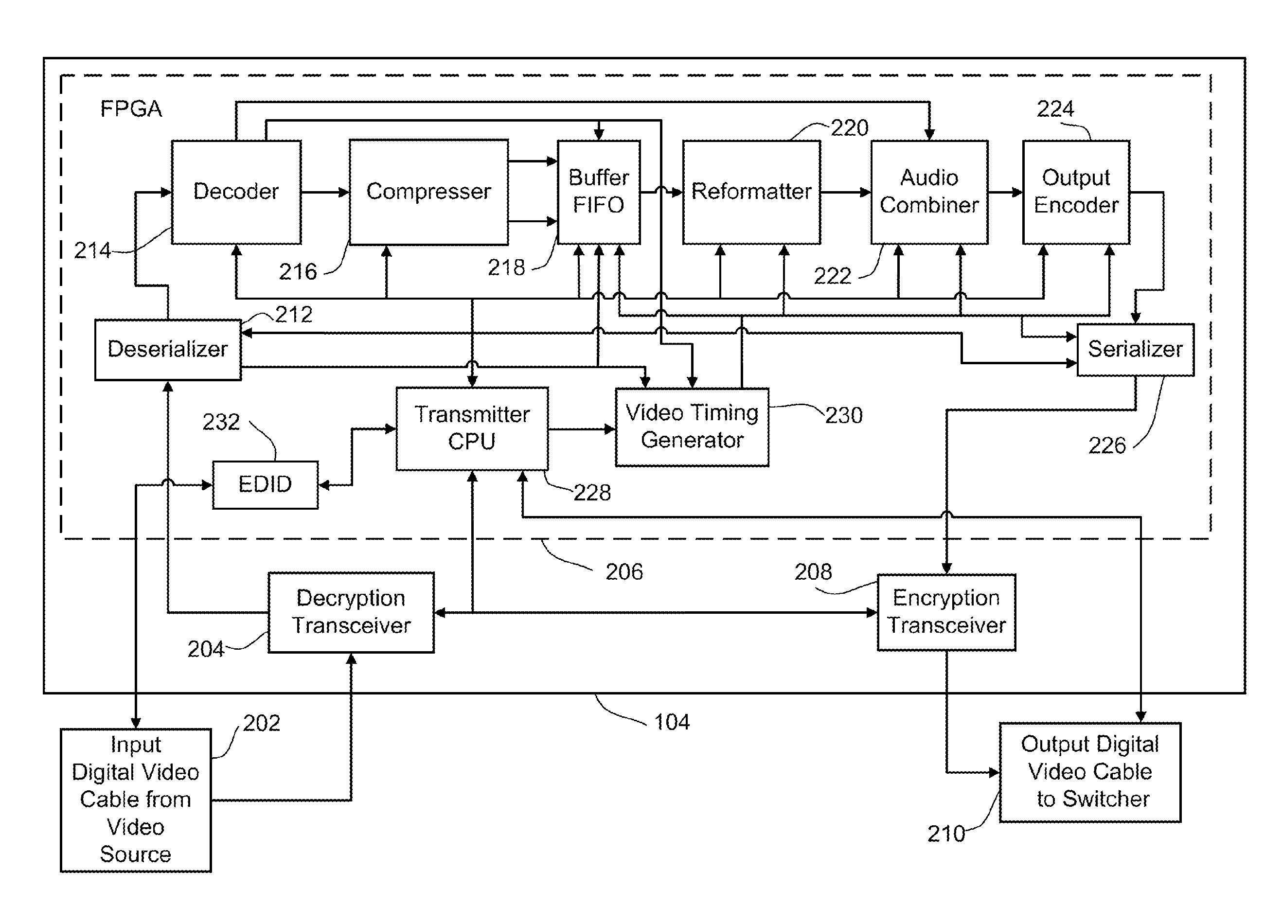
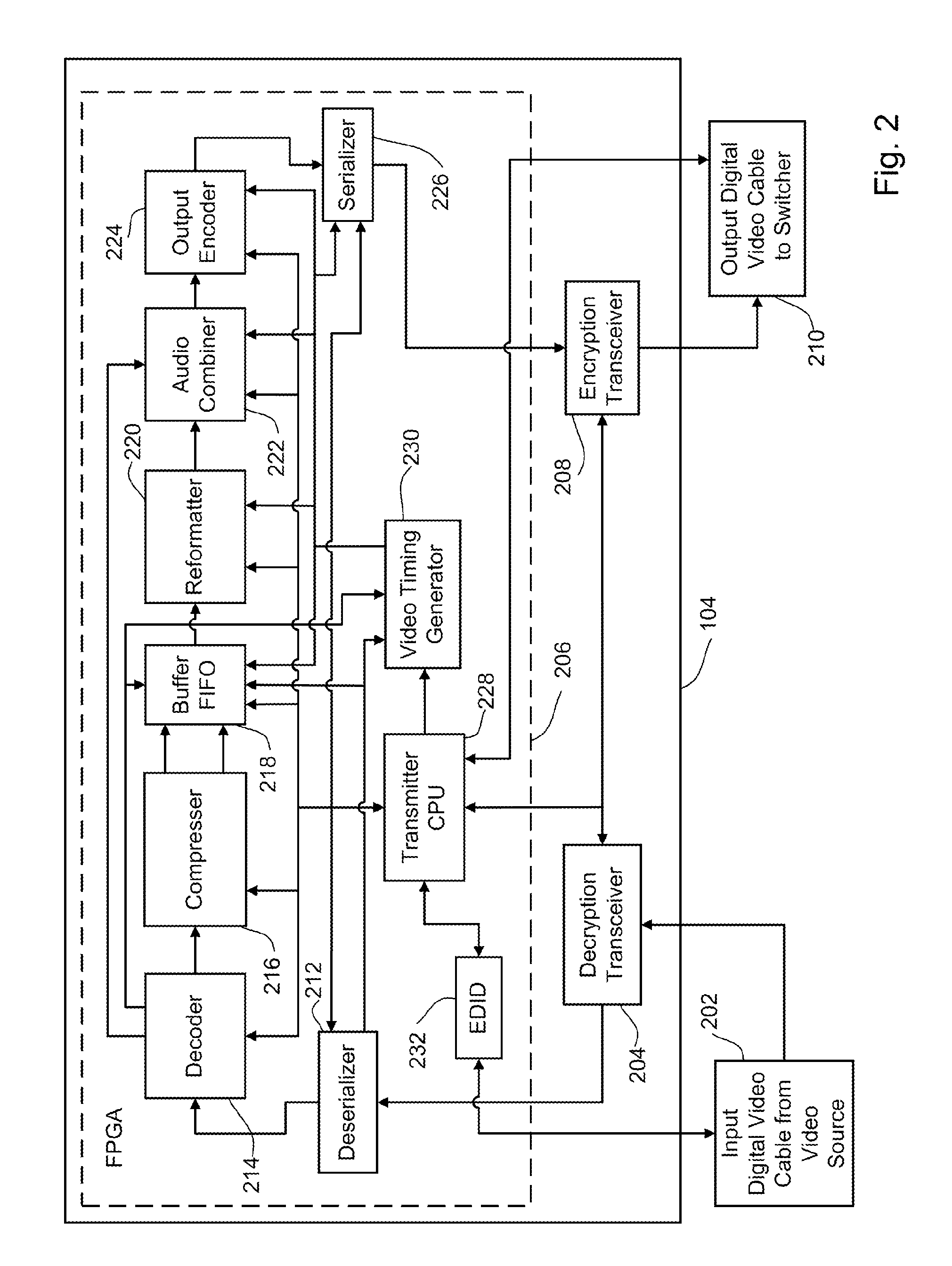
[0140]The present disclosure involves a transmitter for use in an existing vide...


PUM


Abstract

Presented is a video distribution system that includes a transmitter that receives an uncompressed source video signal and includes a compressor for compressing the uncompressed source video signal into a compressed video signal having a bandwidth lower than the bandwidth of the uncompressed source video signal, a reformatter configured for reformatting the compressed video signal to simulate an uncompressed video signal having a bandwidth lower than the bandwidth of the uncompressed video signal. The video distribution system also includes a receiver that receives the compressed video signal that simulates an uncompressed video signal and includes a decompressor configured for decompressing the compressed video signal that simulates an uncompressed video signal into a decompressed video signal, and output port configured for transmitting the decompressed video signal to a display.

Description

BACKGROUND OF THE INVENTION[0001]1. Technical Field[0002]The present invention relates generally to video compression and more particularly to a system and method for compressing video from a video source and then reformatting the compressed video to mimic or simulate uncompressed video with a lower bandwidth than the uncompressed source video and transmitting the compressed video via a video infrastructure that is incapable of supporting the uncompressed source video.[0003]2. Background Art[0004]There are various types of digital video interface standards in use today that are used to transfer and switch uncompressed video and audio signals from one piece of equipment or another. HDMI®, HDBaseT®, and DisplayPort are examples of such interfaces.[0005]Equipment intended to communicate with these video interfaces is necessarily designed with components available at the time of the video system design. Such equipment transmits the uncompressed video and audio signals bit by bit over lo...

Claims


Application Information

Patent Timeline
Patent Type & Authority Applications(United States)
IPC IPC(8): H04N7/01H04N19/44H04N7/015
CPCH04N7/0122H04N19/44H04N7/015H04N7/12G09G5/005G09G5/008G09G2340/02G09G2350/00G09G2360/02G09G2370/042H04N19/40
Inventor LABOSCO, MARKPAGANO, DARIO
Owner CRESTRON ELECTRONICS
Why Eureka
Try Eureka