Apparatus and Method for Monitoring Respiration Volumes and Synchronization of Triggering in Mechanical Ventilation by Measuring the Local Curvature of the Torso Surface

a technology of torso surface and torso sensor, which is applied in the direction of sensors, medical devices, diagnostics, etc., can solve the problems of increasing the morbidity of critically ill patients, affecting the measurement, and adding to the burden on the respiratory system, so as to eliminate sharp bending and poor measurement results

Inactive Publication Date: 2015-10-15
DIASENS D O O
View PDF7 Cites 13 Cited by
  • Summary
  • Abstract
  • Description
  • Claims
  • Application Information

AI Technical Summary

Benefits of technology

[0037]Another advantage of placing the sensor over a torso area with stiff underlying tissues is that this eliminates sharp bending that may lead to buckling of sensors observed in using a large number of sensors with some of them placed over the soft-tissue area (Allsop T. et al., Application of long-period-grating sensors to respiratory Plethysmography, J Biomed Opt. 2007 November-December; 12(6):064003). Sharp bending / buckling of sensors may cause multiple curvatures along the grating and thus lead to poor measurement results.

Problems solved by technology

In non-invasive ventilation, measurement can be affected by air leaks, which is an important problem commonly occurring when oronasal masks are used.
This asynchrony imposes an additional burden on the respiratory system and may increase the morbidity of critically ill patients.
Patient ventilator asynchrony during the triggering process appears in the following forms: autotriggering (triggering in the absence of inspiratory muscle contraction), excessive triggering delay (delay between the beginning of the inspiratory effort and ventilator triggering) and ineffective efforts (the inability of the patient inspiratory effort to trigger the ventilator).
All pneumatic-triggering variables may be affected by air leaks.
Untrained subjects, however, often find it difficult to perform the isovolume maneuver.
For this and similar reasons, although more comfortable for patients than the one using the isovolumetric maneuver, the accuracy of QDC calibration is often questioned.
), “not sufficiently accurate for clinical use” (Werchowski J L, Inductance plethysmography measurement of CPAP-induced changes in end-expiratory lung volume.
The RIP method suffers from a large baseline drift that jeopardizes accurate EELV determination (Neumann P, Evaluation of Respiratory Inductive Plethysmography in Controlled Ventilation, Chest 1998; 113; 443-451) and, consequently, has been largely abandoned (Grivans C. et al., Positive end-expiratory pressure-induced changes in end-expiratory lung volume measured by spirometry and electric impedance tomography Acta Anaesthesiol Scand 2011; 55: 1068-1077).
A practical problem encountered in inductive plethysmography is that the calibration coefficients depend on the position of the bands around thorax and abdomen.
Consequently, the application of inductive plethysmography during sleep includes risk of providing inaccurate volume values, due to the displacement of the bands due to patient movement during sleep.
Thus, RIP may produce poor correlation with a direct measurement of tidal volume by pneumotachograph during sleep (Whyte K F et al., Accuracy of respiratory inductive plethysmograph in measuring tidal volume during sleep.
The main drawback of NAVA technology is its invasiveness.
It uses a catheter placed into the patient's esophagus and requires draining gastric content via the nasogastric tube prior to catheter placement, etc., thus making the ventilation treatment more complicated and increasing risk and patient discomfort.
This procedure may be time consuming, which is another potential drawback of the NAVA method.
Along with the promising results, some drawbacks of the technique were reported (Allsop T. et al., Application of long-period-grating sensors to respiratory Plethysmography, J Biomed Opt. 2007 November-December; 12(6):064003): a) there is an overall constant volume error observed between successive measurements, so that the absolute measured volume cannot be inferred from a simple linear combination of the outputs, probably due to the movement of the vest between successive measurements, and b) sharp bending or buckling of the sensors may cause a nonuniform curvature, which could significantly distort the Shape of the LPGs' attenuation bands, leading to unreliable results.

Method used


Image

  • Apparatus and Method for Monitoring Respiration Volumes and Synchronization of Triggering in Mechanical Ventilation by Measuring the Local Curvature of the Torso Surface
  • Apparatus and Method for Monitoring Respiration Volumes and Synchronization of Triggering in Mechanical Ventilation by Measuring the Local Curvature of the Torso Surface
  • Apparatus and Method for Monitoring Respiration Volumes and Synchronization of Triggering in Mechanical Ventilation by Measuring the Local Curvature of the Torso Surface

Examples


Embodiment Construction

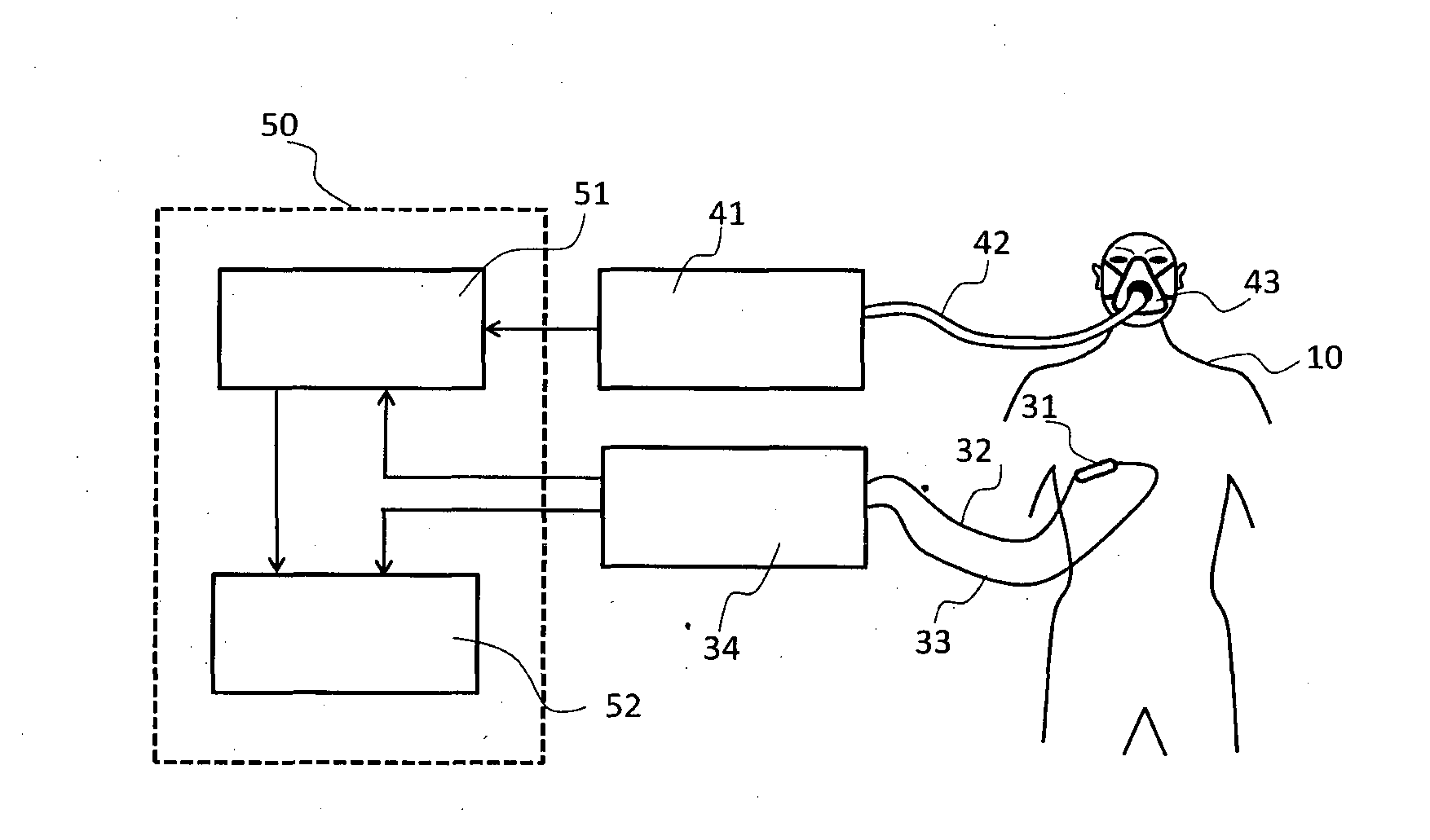
[0048]FIG. 1. shows a block diagram of an embodiment of a system for measuring respiratory volumes in accordance with the presented invention. Referring to FIG. 1, as an example of the sensor working principle, an LPG curvature sensor 31 is attached the patient's 10 lower ribs area, preferably between the ribs 6 and 8, between the lines parallel with the sternum, at about 10 cm left and right from the sternum. The sensor may be self-adhesive, placed on an adhesive tape, or attached otherwise. Two optical fibers 32 and 33 are connecting the LPG sensor to an interrogation module 34, which converts the optical signal from the LPG sensor 31 to a digital signal proportional to the sensor curvature. Since the measurements using LPG sensors are based on the transmitted signal detection, the direction of the optical signal propagation in the first optical fiber 32 is from the interrogation module 34 to the LPG curvature sensor 31, while in the other optical fiber 33 the transmitted optical ...


PUM


Abstract

The invention is related to a device and method for monitoring respiration, movements in mechanical ventilation in order to provide a non-pneumatic triggering variable for achieving patient-ventilator asynchrony and continuous measurement of tidal volumes. The method is based on measuring the curvature of the patient's torso surface using a single LPG (Long Period Grating) fiber-optic sensor attached to a surface of the torso in an area having high stiffness of the underlying tissue, such as the area of the lower ribs close to the sternum.

Description

TECHNICAL FIELD[0001]The present invention relates to a sensor for measuring the respiration volume by means of measuring thoracic movements, specifically the local curvature variation of the surface of the human torso.BACKGROUND ART[0002]This invention relates to a method and apparatus for continuous monitoring of the respiration of patients, particularly critically ill patients in intensive care units. In medicine, mechanical ventilation is a method to mechanically assist or replace spontaneous breathing. This may involve a machine called ventilator. There are two main types of mechanical ventilation: 1) invasive ventilation, using tracheal intubation (a tube is inserted through the nose or mouth and advanced into the trachea) and 2) non-invasive ventilation, using an oronasal mask or a mouthpiece. In mechanical ventilation, measurement (or at least an estimate) of the tidal volume (Vt, the volume of air moved into or out of the lungs during quiet breathing) is necessary to ensure...

Claims


Application Information

Patent Timeline
Patent Type & Authority Applications(United States)
IPC IPC(8): A61B5/113A61B5/0402A61B5/0205A61M16/00A61B5/00
CPCA61B5/1135A61M16/0069A61B5/7203A61B5/0205A61B5/0402A61M2230/40A61B5/0245A61B2562/0266A61B2560/0223A61B5/09A61M2205/3303A61B5/091A61B2560/0238A61B5/33
Inventor BOJOVIC, BOSKOVUKCEVIC, MIODRAGPETROVIC, JOVANAPETROVIC, MARIJAILIC, IGORDANICIC, ALEKSANDARALLSOP, THOMASHADZIEVSKI, LJUPCO
Owner DIASENS D O O
Why Eureka
Try Eureka