
Pipe connection for conducting a fluid that is under pressure

Active Publication Date: 2015-10-15
SIEMENS ENERGY GLOBAL GMBH & CO KG
View PDF16 Cites 2 Cited by
  • Summary
  • Abstract
  • Description
  • Claims
  • Application Information

AI Technical Summary

Benefits of technology

The invention aims to prevent leaks and reduce the breakaway torque of the union nut in cases of dropping temperature gradients. This is achieved by providing a thermal barrier in the axial section of the sealing face of the inner cone, on the inner pipe face. The thermal barrier takes the form of a thermal barrier pipe that is designed to prevent heat from being conducted directly into the cone of the inner sealing face. The invention also includes a locknut that can further increase the breakaway torque of the union nut.

Problems solved by technology

This can have the result that, in the case of dropping temperature gradients, the cone of the inner sealing face shrinks faster than the cone of the outer sealing face.
This can on one hand lead to leaks and on the other hand reduce the breakaway torque of the union nut.

Method used


Image

  • Pipe connection for conducting a fluid that is under pressure
  • Pipe connection for conducting a fluid that is under pressure

Examples


Embodiment Construction

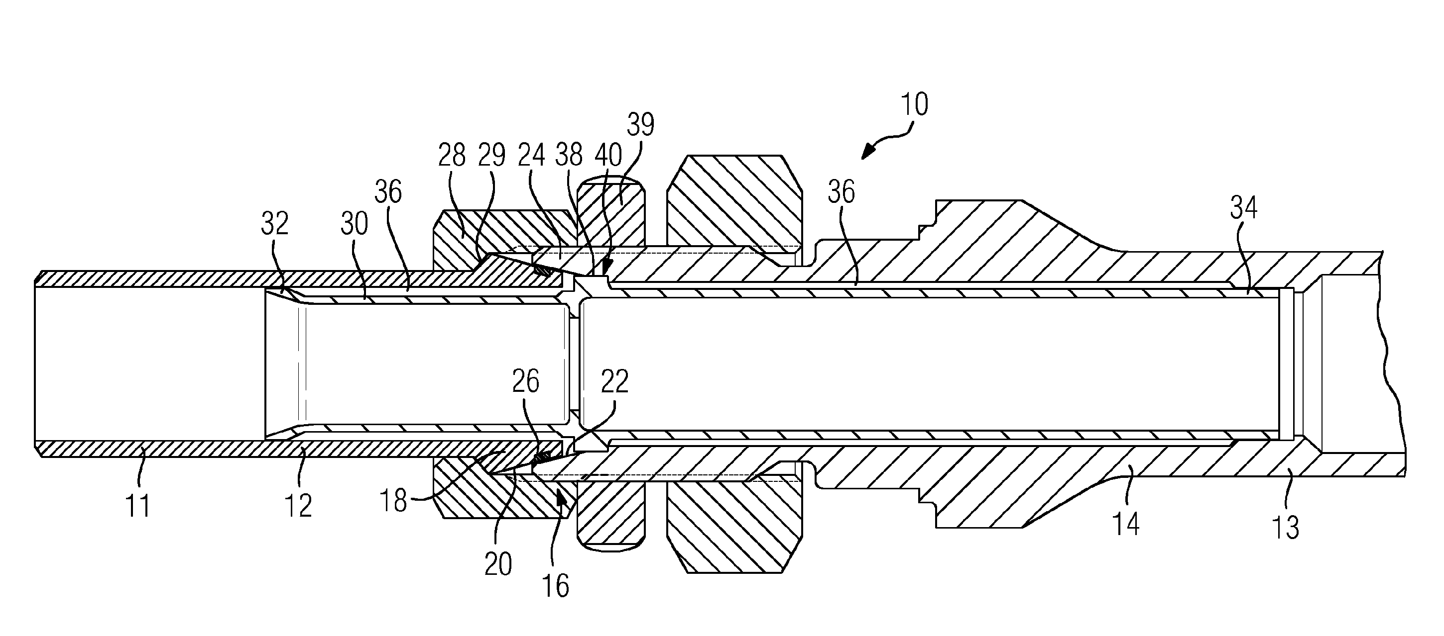
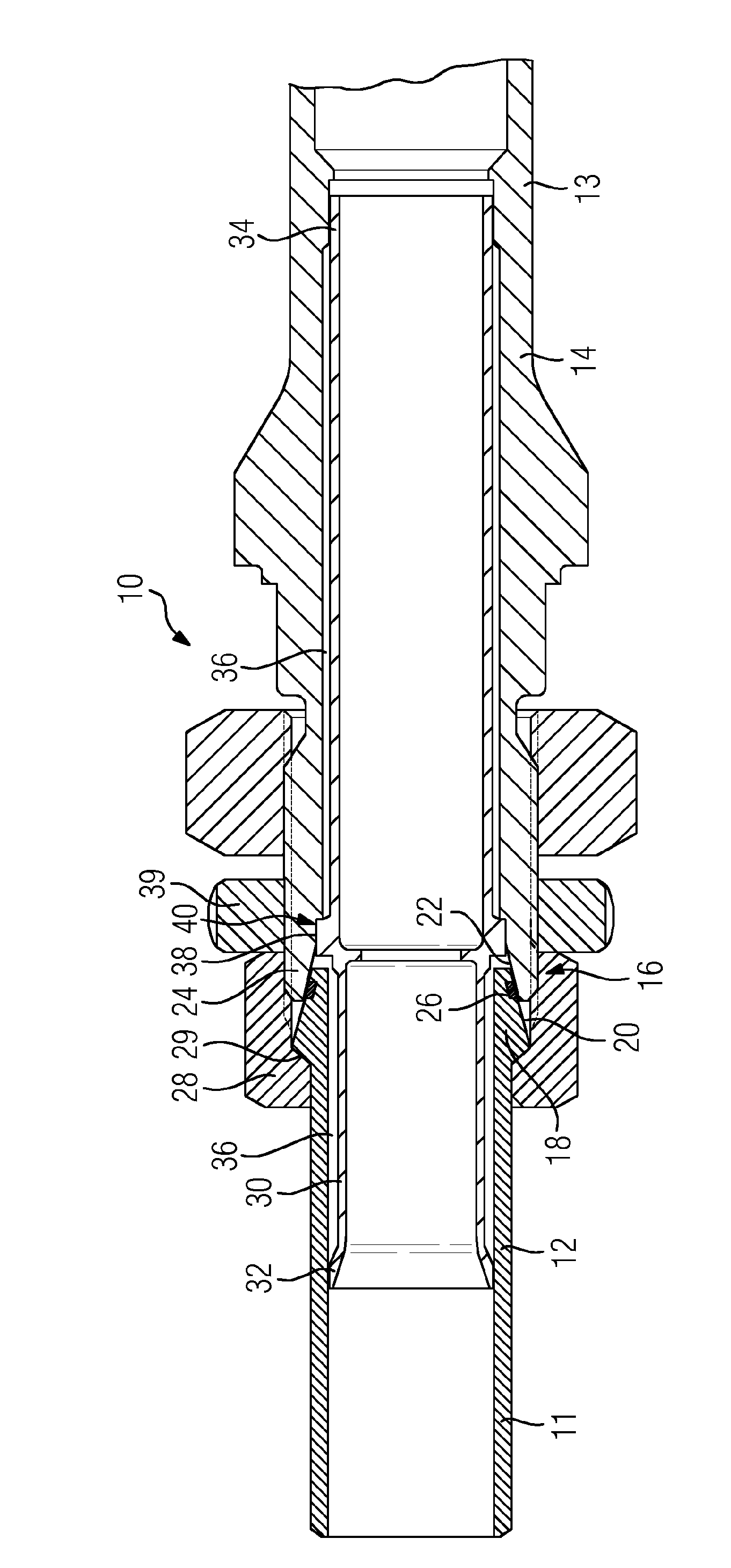
[0019]The single FIGURE shows, in longitudinal section, a pipe connection 10 for conducting a fluid that is under pressure. In that context, the pipe connection 10 comprises two connection pieces 12, 14 which are connected for a cone clamping connection 16. To that end, the first connection piece 12 has a cone 18 with an outward-oriented conical sealing face 20. The second connection piece 14 has, at an inclination which corresponds to the sealing face 20, an also conical sealing face 22, as part of a cone 24. The cone 24 forms the outer cone and the cone 18 forms the inner cone of the cone clamping connection.

[0020]In the sealing face 20 there is provided an endless circumferential annular groove 26 for receiving graphite as sealant. The two connection pieces 12, 14 are connected to one another with the aid of a union nut 28. Specifically, to that end, the union nut 28 is screwed onto the second connection piece 14, wherein the union nut 28 presses a conical shaft collar 29, as rea...


PUM


Abstract

A pipe connection for conducting a fluid that is under pressure is provided, having two tubular connection parts for a conical clamping connection, which are screwed together by a union nut while one is inserted in the other, wherein each connection part has a conical sealing surface that contacts the other in a sealing manner and wherein an annular groove is provided in one of the sealing surfaces. In order to enable the pipe connection also to conduct a fluid having cycling or varying temperature, the inner of the two connection parts has thermal insulation on the inside of the pipe at least in the axial segment of the sealing surface of the connection part, wherein the thermal insulation tube has a cam or a collar on the outer surface, which engages in a recess, which is axially bounded by the two connection parts.

Description

CROSS REFERENCE TO RELATED APPLICATIONS[0001]This application is the US National Stage of International Application No. PCT / EP2013 / 070887 filed Oct. 8, 2013, and claims the benefit thereof. The International Application claims the benefit of German Application No. DE 102012218727.8 filed Oct. 15, 2012. All of the applications are incorporated by reference herein in their entirety.FIELD OF INVENTION[0002]The invention relates to a pipe connection for conducting a fluid that is under pressure, comprising two tubular connection pieces which are screwed together by means of a union nut, being plugged one into the other in the manner of a cone clamping connection, wherein each connection piece has a conical sealing face which bears in a sealing manner against the other of the two sealing faces.BACKGROUND OF INVENTION[0003]Pipe connections of the type mentioned in the introduction are very well known from the prior art. For example, DE 1 960 933 U discloses a connection piece, as part of ...

Claims


Application Information

Patent Timeline
IPC IPC(8): F16L19/00F16L59/00F16L21/035
CPCF16L19/00F16L59/00F16L21/035F16L19/005F16L19/025F16L59/181F16L59/18
Inventor BOTTCHER, ANDREASDUMLER, HARTWIGHESSE, WERNERKOCK, BORIS FERDINANDLAPP, PATRICKOTTE, LARSSEIDEL, FALKSTAPPER, PHILIPPSTARING, SASCHAWEBER, GERD
Owner SIEMENS ENERGY GLOBAL GMBH & CO KG
Learn More