

Photoacoustic imaging device
a technology of imaging device and photoacoustic field, which is applied in the direction of diagnostic recording/measuring, instruments, applications, etc., can solve the problems of signal that has been affected by noise produced, vibration of ultrasonic transducer (mistaken operation) by noise, and end up being acquired, so as to achieve the effect of suppressing the reception circui
- Summary
- Abstract
- Description
- Claims
- Application Information
AI Technical Summary
Benefits of technology
Problems solved by technology
Method used
Image

Examples
first embodiment
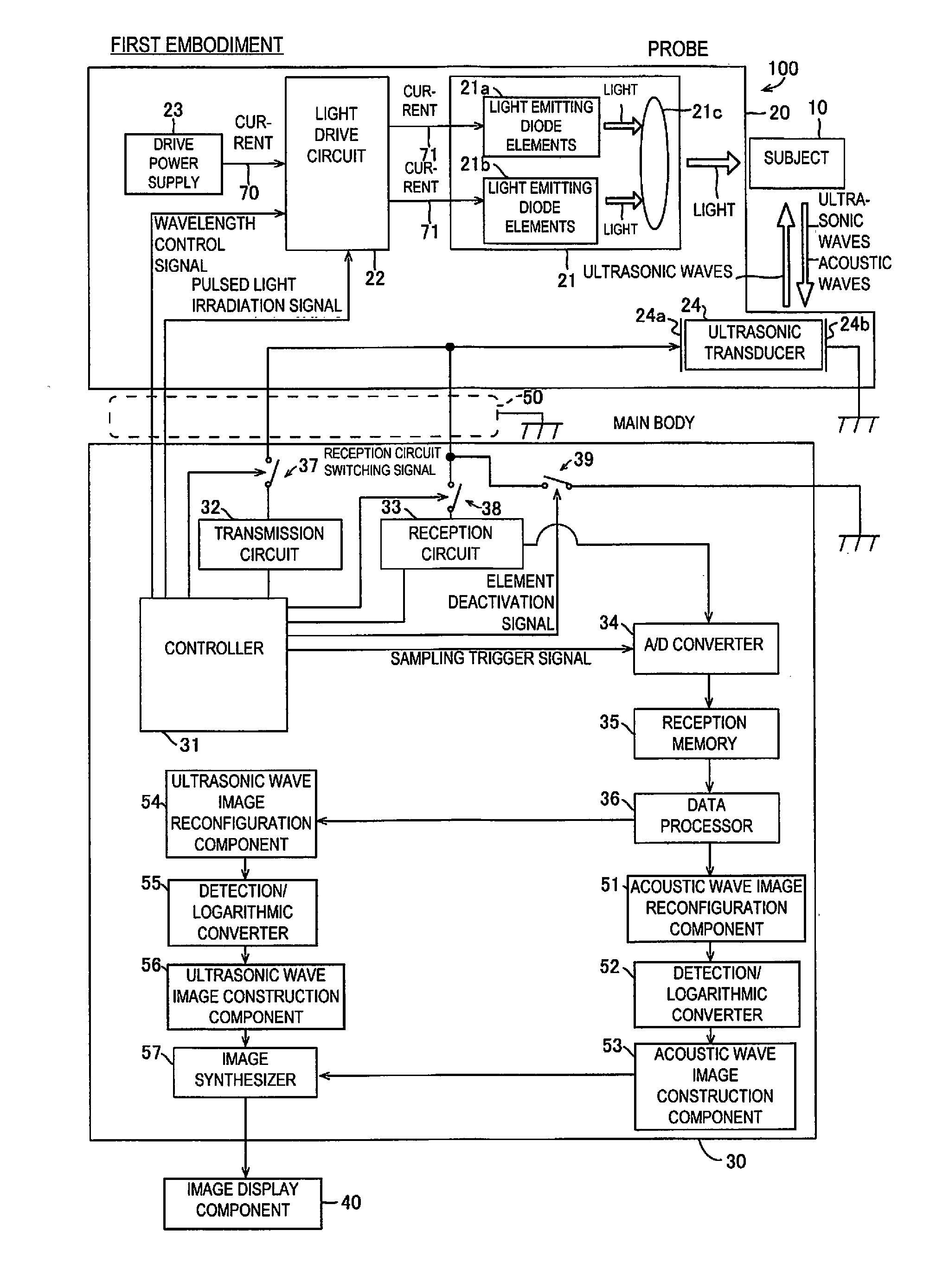
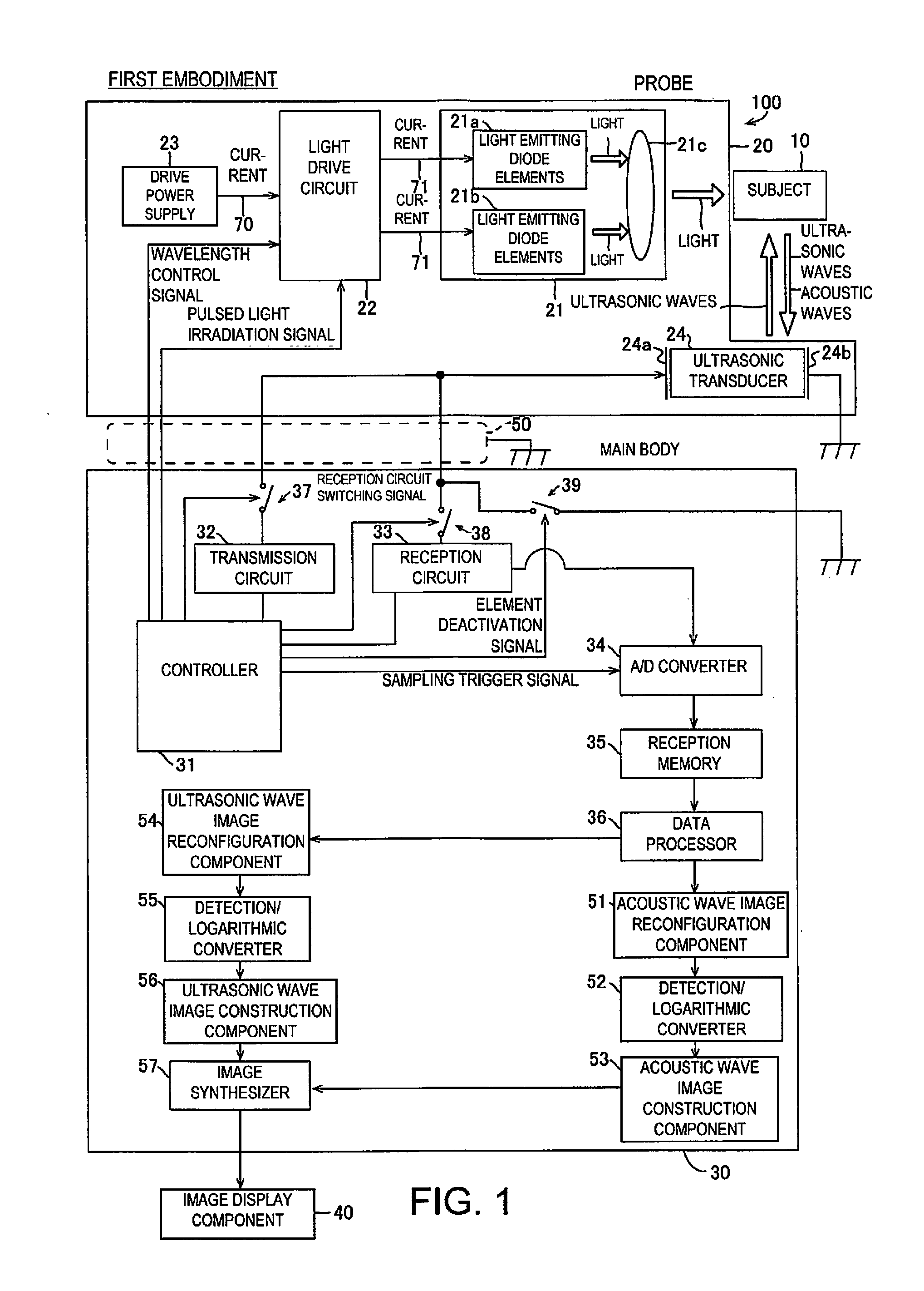
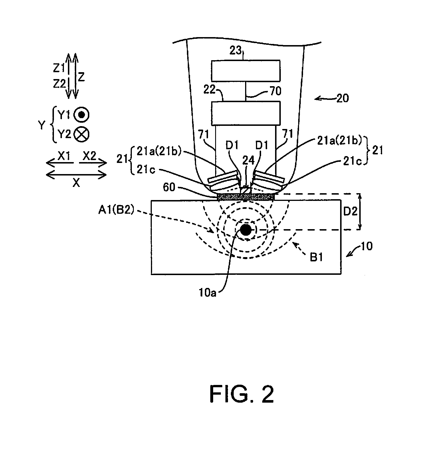
[0027]The configuration of a photoacoustic imaging device 100 in accordance with a first embodiment will be described through reference to FIGS. 1 to 3.
[0028]As shown in FIG. 1, the photoacoustic imaging device 100 in accordance with the first embodiment includes a probe 20 that detects acoustic wave signals from inside a subject 10, a main body 30 that processes and images the acoustic wave signals detected by the probe 20, and an image display component 40 that displays the images processed by the main body 30. The probe 20 and the main body 30 are connected via a cable 50 composed of a cable that is shielded against electromagnetic waves and is covered by a metal mesh, etc. The main body 30 is an example of the “device main body” of the present invention.
[0029]As shown in FIG. 1, the probe 20 includes a light source 21, a light drive circuit 22, a drive power supply 23, and an ultrasonic transducer 24. The light source 21 includes a plurality of light emitting diode elements 21a ...
second embodiment
[0094]The configuration of a photoacoustic imaging device 101 in accordance with a second embodiment will now be described through reference to FIG. 8. In view of the similarity between the first and second embodiments, the parts of the second embodiment that are identical to the parts of the first embodiment will be given the same reference numerals as the parts of the first embodiment. Moreover, the descriptions of the parts of the second embodiment that are identical to the parts of the first embodiment may be omitted for the sake of brevity. In the second embodiment, unlike with the photoacoustic imaging device 100 in which the deactivation switch 39 is provided to the main body 30, a deactivation switch 39a is provided to a probe 20a.
[0095]As shown in FIG. 8, the photoacoustic imaging device 101 in accordance with the second embodiment includes the probe 20a that irradiates the subject 10 with pulsed light from the light source 21 by disposing the light source 21 and the ultra...
third embodiment
[0109]The configuration of a photoacoustic imaging device 102 in accordance with a third embodiment will now be described through reference to FIGS. 8 and 9. In view of the similarity between the first to third embodiments, the parts of the third embodiment that are identical to the parts of the first or second embodiment will be given the same reference numerals as the parts of the first or second embodiment. Moreover, the descriptions of the parts of the third embodiment that are identical to the parts of the first or second embodiment may be omitted for the sake of brevity. In the third embodiment, a controller 31a is configured so that the leading edge and trailing edge of the waveform of the element deactivation signal for controlling the deactivation switching will have a shape that is blunter or more gradual than a rectangular waveform.
[0110]As shown in FIG. 8, the photoacoustic imaging device 102 in the third embodiment is similar to the photoacoustic imaging device 101 in t...
PUM
 Abstract
Description
Claims
Application Information