Position detector and liquid ejecting apparatus incorporating the same

a technology of liquid ejecting apparatus and detector, which is applied in the direction of printing mechanism, spacing mechanism, printing, etc., can solve the problems of ink mist attachment, disadvantageous effect, diffracted light passing through the light transmitting section, etc., and achieve the effect of suppressing the reception of excessively diffused or diffracted ligh

Active Publication Date: 2007-03-15
SEIKO EPSON CORP
View PDF20 Cites 1 Cited by
  • Summary
  • Abstract
  • Description
  • Claims
  • Application Information

AI Technical Summary

Benefits of technology

[0036] In this case, the reception of the excessively diffused or diffracted light can be suppressed even when the pigment-base ink which tends to cause the light diffraction is attached onto the transparent member.

Problems solved by technology

In such the encoder, recently, there is a problem of attachment of ink mist.
In a case where the ink mist is attached onto the light transmitting section of the scale, light which passes through the light transmitting section is diffracted and causes a disadvantageous effect.

Method used


Image

  • Position detector and liquid ejecting apparatus incorporating the same
  • Position detector and liquid ejecting apparatus incorporating the same
  • Position detector and liquid ejecting apparatus incorporating the same

Examples


Embodiment Construction

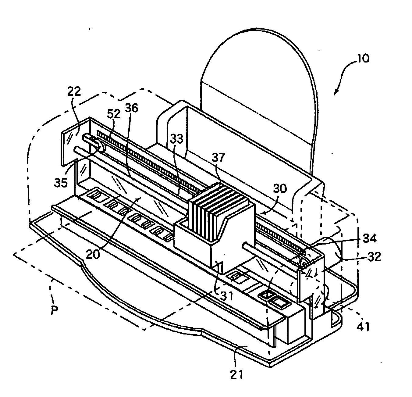
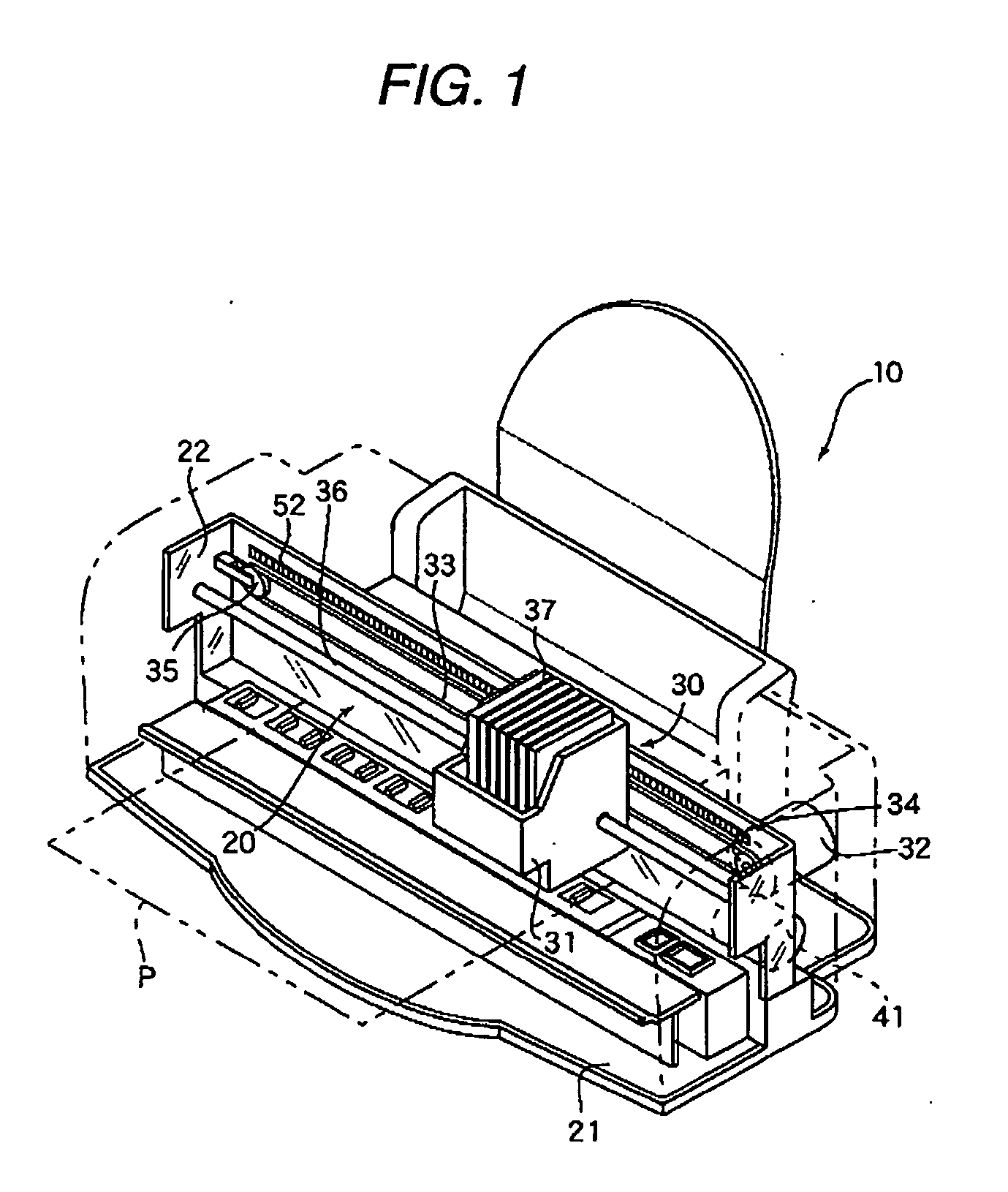
[0048] A position detector according to one embodiment of the invention and a printer 10 using this position detector will be described below with reference to FIGS. 1 to 10. The printer 10 in the embodiment is an ink jet type printer. However, such the ink jet printer, as long as it can eject ink to perform printing, may adopt any ejection method.

[0049] In the following description, a “downside” indicates a side on which the printer 10 is placed, and an “upside” indicates a side apart from the side on which the printer 10 is placed. A direction where a carriage 31 described later moves is taken as a primary scanning direction, and a direction which is orthogonal to the primary scanning direction and where a printed subject P is transported is taken as a secondary scanning direction.

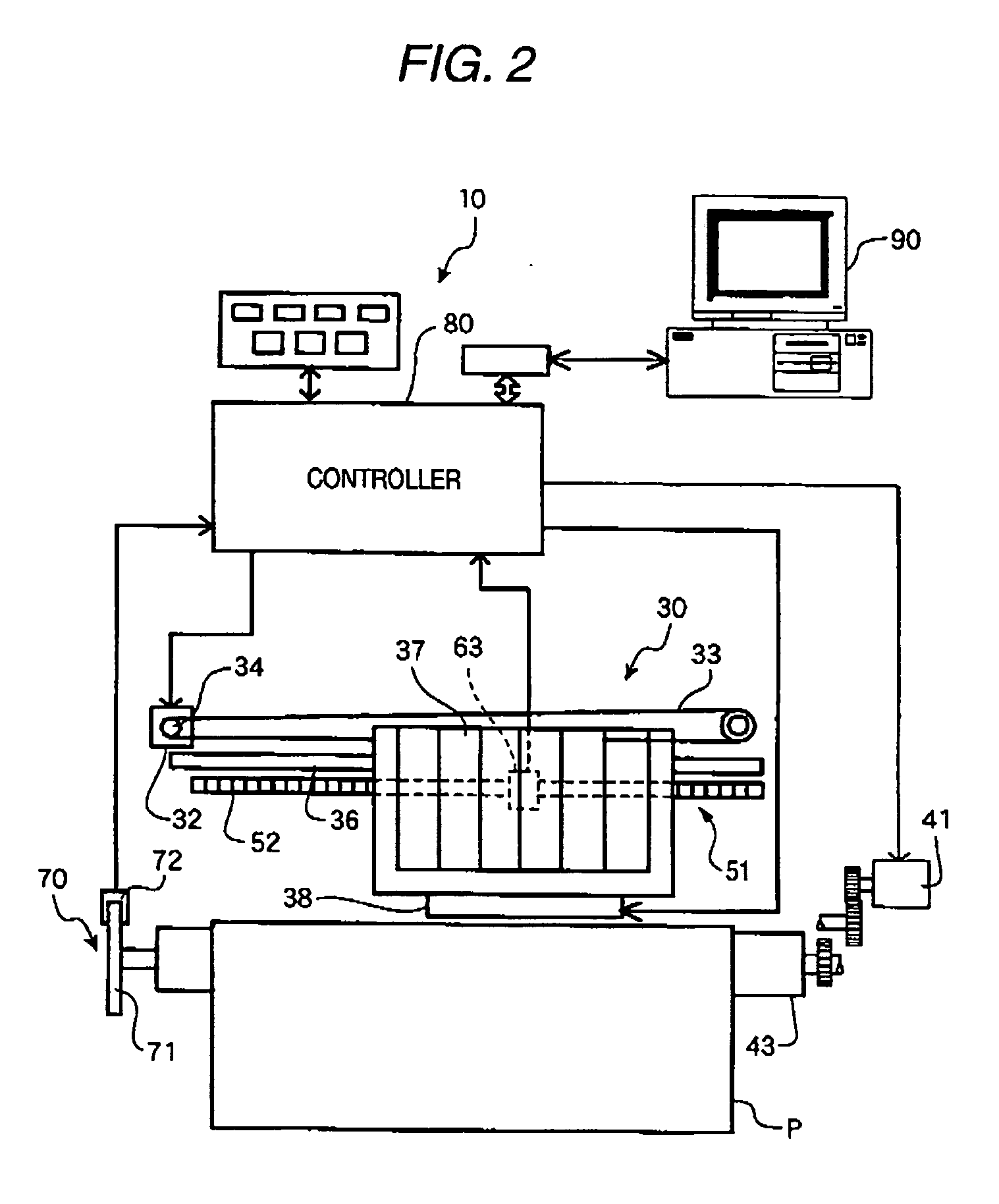
[0050] As shown in FIG. 1, the printer 10 comprises a housing 20, a carriage driving mechanism 30, a sheet transporting mechanism 40, a linear encoder 50, a rotary encoder 70, and a controller 80.

[005...


PUM


Abstract

A light emitter is operable to emit light. A light receiver is adapted to receive the light emitted from the light emitter, and operable to output a signal in accordance with an amount of the received light, thereby detecting a position of an object. At least one transparent member is disposed between the light emitter and the light receiver. A first line pattern is provided with the transparent member so as to oppose the light emitter, and includes first light transmitting sections and first light shielding sections which are alternately arranged in a first direction with a first pitch. A second line pattern is provided with the transparent member so as to oppose the light receiver, and includes second light transmitting sections and second light shielding sections which are alternately arranged in the first direction with a second pitch. Each of the first light transmitting sections is adapted to allow the light emitted from the light emitter to pass through. Each of the first light shielding sections is adapted to shield the light emitted from the light emitter. Each of the second light transmitting sections is adapted to allow light having passed through the transparent member. Each of the second light shielding sections is adapted to shield the light having passed through the transparent member.

Description

BACKGROUND [0001] 1. Technical Field [0002] The present invention relates to a position detector and a liquid ejecting apparatus incorporating the same. [0003] 2. Related Art [0004] In an ink jet printer, a carriage and a printed subject such as paper are driven by a motor. Incidentally, in order to perform position control and speed control, an encoder is generally used. The encoder includes a photo sensor and a scale. The photo sensor includes a light emitting element and a light receiving element the scale includes a light transmitting section which transmits light emitted from the light emitting element, and a light shielding section which shields light emitted from the light emitting element. These light transmitting section and light shielding section are repetitively arranged at a fixed pitch. [0005] In such the encoder, recently, there is a problem of attachment of ink mist. Namely, recent printers which perform printing with high precision can eject minute ink droplets from...

Claims


Application Information

Patent Timeline
Patent Type & Authority Applications(United States)
IPC IPC(8): B41J2/01
CPCB41J19/207
Inventor NAKATA, SATOSHIIGARASHI, HITOSHI
Owner SEIKO EPSON CORP
Why Eureka
Try Eureka