Method for improving the quality of voice transmission via a radio interface

a radio interface and voice technology, applied in the field of improving the quality of voice transmission via radio interface, can solve the problems of local signal extinction, multipath reception and radio wave superimposition, and impair the speech quality experienced, and achieve the effect of reducing channel-specific interference, low data rate, and least delay

Inactive Publication Date: 2008-11-25
UNIFY GMBH & CO KG
View PDF17 Cites 2 Cited by
  • Summary
  • Abstract
  • Description
  • Claims
  • Application Information

AI Technical Summary

Benefits of technology

[0006]To reduce these impairments what are known as equalizers are used in narrow band voice transmission systems, such as GSM, to suppress multipath reception. However, in the case of radio transmissions with a higher bandwidth requirement, for example with DECT or WLAN systems, an equalizer of this sort requires much greater production expenditure. In addition, an equalizer would not improve the receiving situation in the case of local signal extinction.
[0008]An object of the present invention is to disclose a method for improving the quality of wireless voice transmission which can be achieved with little expenditure.
[0011]The delayed transmission of a voice data packet representing the same voice portion can considerably reduce an error frequency in the voice data packets to be processed further, in particular in the case of moving users and thus significantly improve the voice transmission quality. The distribution of the first and second voice data packets between various time intervals makes the voice transmission less sensitive to brief radio interference, for example as a result of ignition sparks, and in particular to a brief passage of a receiving antenna of the radio interface moved with the user through spaces with local signal extinction (oscillation nodes). Thus even in an environment where reception is difficult high voice transmission quality can be ensured without additional antennae or receiving circuits being necessary.
[0013]According to a first embodiment, the second voice data packet can be transmitted on a different transmission channel, or via a different logical link of the radio interface, to the first voice data packet. An effect of channel-specific interference can thus be reduced. With a DECT radio interface, a speech connection with a transmission rate of 32 kbit / s, for example, can be distributed between at least two data channels with a total of at least 64 kbit / s. With a WLAN radio interface a speech connection can accordingly be distributed between at least two logical channels or logical links.

Problems solved by technology

In environments where reception is difficult and with a large number of radio wave-reflecting surfaces, for example in or between buildings, frequent radio reflections lead to multipath reception and radio wave superimpositions.
In this case destructive interference or oscillation nodes frequently occur which at some spatial locations can lead to local signal extinctions.
A mobile terminal which, once a speech connection has been established, is moved by its user in an environment of this type, where reception is difficult, frequently sweeps such locations with signal extinction, or at least signal reduction, during the movement.
This usually becomes noticeable during a conversation as a result of clicking noises or an interruption in transmission, which the user generally finds very irritating, and considerably impairs the speech quality experienced.
However, in the case of radio transmissions with a higher bandwidth requirement, for example with DECT or WLAN systems, an equalizer of this sort requires much greater production expenditure.
In addition, an equalizer would not improve the receiving situation in the case of local signal extinction.
However, as an additional antenna, and as a rule an additional receiving circuit, is required in this case, production is relatively expensive.

Method used


Image

  • Method for improving the quality of voice transmission via a radio interface
  • Method for improving the quality of voice transmission via a radio interface

Examples


Embodiment Construction

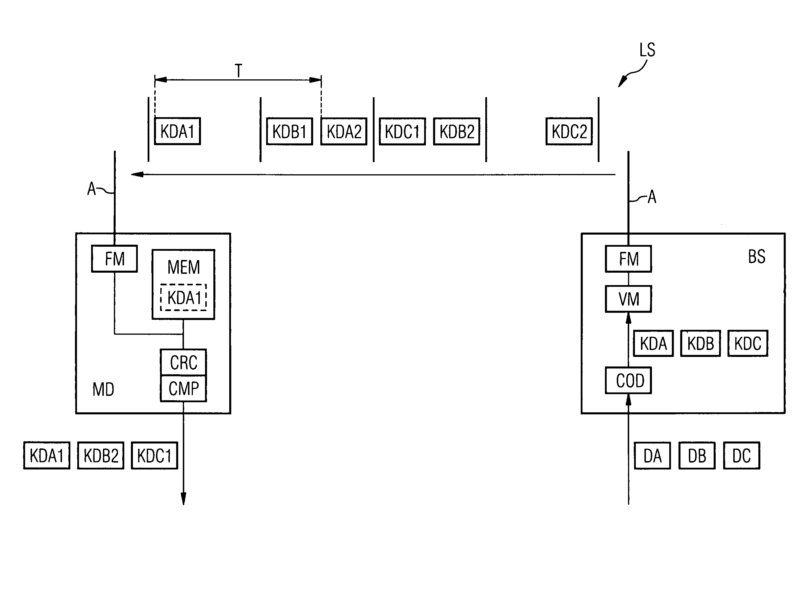
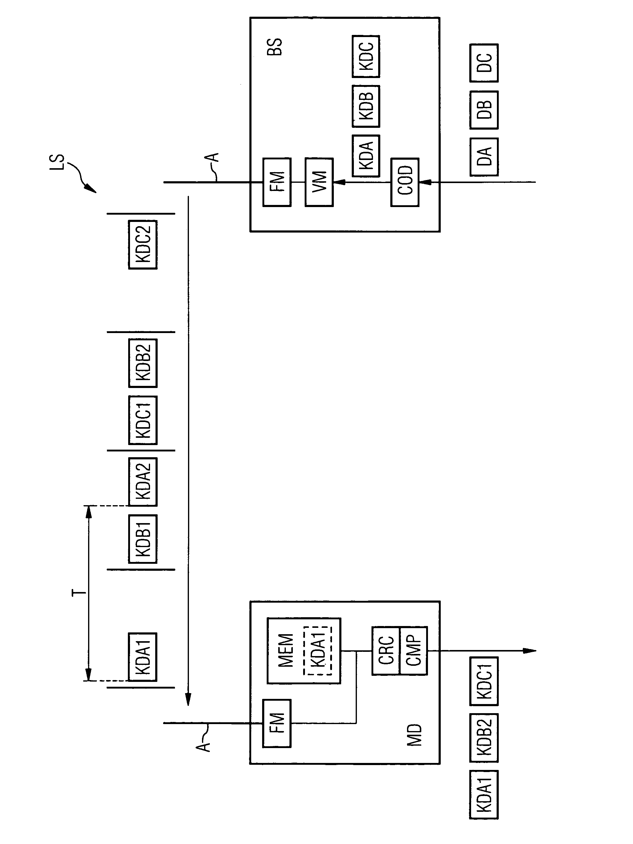
[0020]The figure shows diagrammatically a base station BS and mobile terminal equipment MD. The base station BS can, for example, be achieved according to the DECT or GSM standards or as what is known as a WLAN access point. The mobile terminal equipment MD can, for example, be a cordless telephone according to the DECT standard, a mobile phone according to the GSM standard or another piece of mobile terminal equipment, such as a laptop or PDA (Personal Digital Assistant) with a WLAN interface.

[0021]The mobile terminal equipment MD is coupled via a radio interface LS to the base station BS and it is assumed that there is a wireless real time speech connection. The radio interface LS is indicated in the figure by a horizontal arrow and can, for example, be configured according to the DECT or GSM standard or according to an IEEE-802.11 WLAN standard. The radio interface LS preferably comprises a plurality of transmission channels for voice and / or data transmission, so a plurality of l...


PUM


Abstract

After a predetermined period of time has lapsed after transmission of a voice data packet representing a first voice section a second voice data packet representing the same voice section is transmitted. On the receiving end, a value for the transmission quality is determined for the first and for the second voice data packet and the one of the two voice data packets is processed that has the better transmission quality.

Description

CROSS REFERENCE TO RELATED APPLICATIONS[0001]This application is the US National Stage of International Application No. PCT / EP2004 / 051730, filed Aug. 5, 2004 and claims the benefit thereof. The International Application claims the benefits of German application No. 10345166.8 DE filed Sep. 29, 2003, both of the applications are incorporated by reference herein in their entirety.FIELD OF INVENTION[0002]The present invention relates to a method for improving the quality of voice transmission via a radio interface.BACKGROUND OF INVENTION[0003]Modern communications systems increasingly comprise mobile communications devices, in particular mobile voice communications devices. With wireless voice transmission voice signals to be transmitted in real time are usually digitized and transmitted via a radio interface in the form of data packets. Various transmission standards, such as DECT (Digital European Cordless Telecommunications) or GSM (Global System for Mobile Communications) have esta...

Claims


Application Information

Patent Timeline
Patent Type & Authority Patents(United States)
IPC IPC(8): H04B7/00H04B1/38H04J1/00H04J1/02H04J3/18H04J3/24H04M1/00H04L1/08
CPCH04L1/08
Inventor HEITMANN, JURGEN
Owner UNIFY GMBH & CO KG
Why Eureka
Try Eureka