Array antenna for suppressing back signal and method for designing the same

a back signal and array antenna technology, applied in the direction of antennas, antenna details, electrical devices, etc., can solve the problem of limited back signal possible zero point angle 134/b>

Inactive Publication Date: 2008-03-04
JEUNG HA JAE
View PDF7 Cites 2 Cited by
  • Summary
  • Abstract
  • Description
  • Claims
  • Application Information

AI Technical Summary

Benefits of technology

[0012]It is an object of the present invention to provide an antenna device which forms a main beam of various angles which is needed for the front direction and suppresses reception of the back signal at intensity of −30 db ( 1 / 1000) with respect to all back directions of 180 degree (e.g., 90˜270 degree if it is assumed that the front direction is 0 degree), compared to the main beam and a method for designing the same.

Problems solved by technology

However, the conventional isolation antenna has a problem in that a possible zero point angle 134 of the back signal is limited by size and number of the electric wave obstacles.

Method used


Image

  • Array antenna for suppressing back signal and method for designing the same
  • Array antenna for suppressing back signal and method for designing the same
  • Array antenna for suppressing back signal and method for designing the same

Examples


Embodiment Construction

[0024]The present invention will now be described more fully hereinafter with reference to the accompanying drawings, in which preferred embodiments of the invention are shown. This invention may, however, be embodied in different forms and should not be construed as limited to the embodiments set forth herein. Rather, these embodiments are provided so that this disclosure will be thorough and complete, and will fully convey the scope of the invention to those skilled in the art. In the drawings, the thickness of layers and regions are exaggerated for clarity. Like numbers refer to like elements throughout the specification.

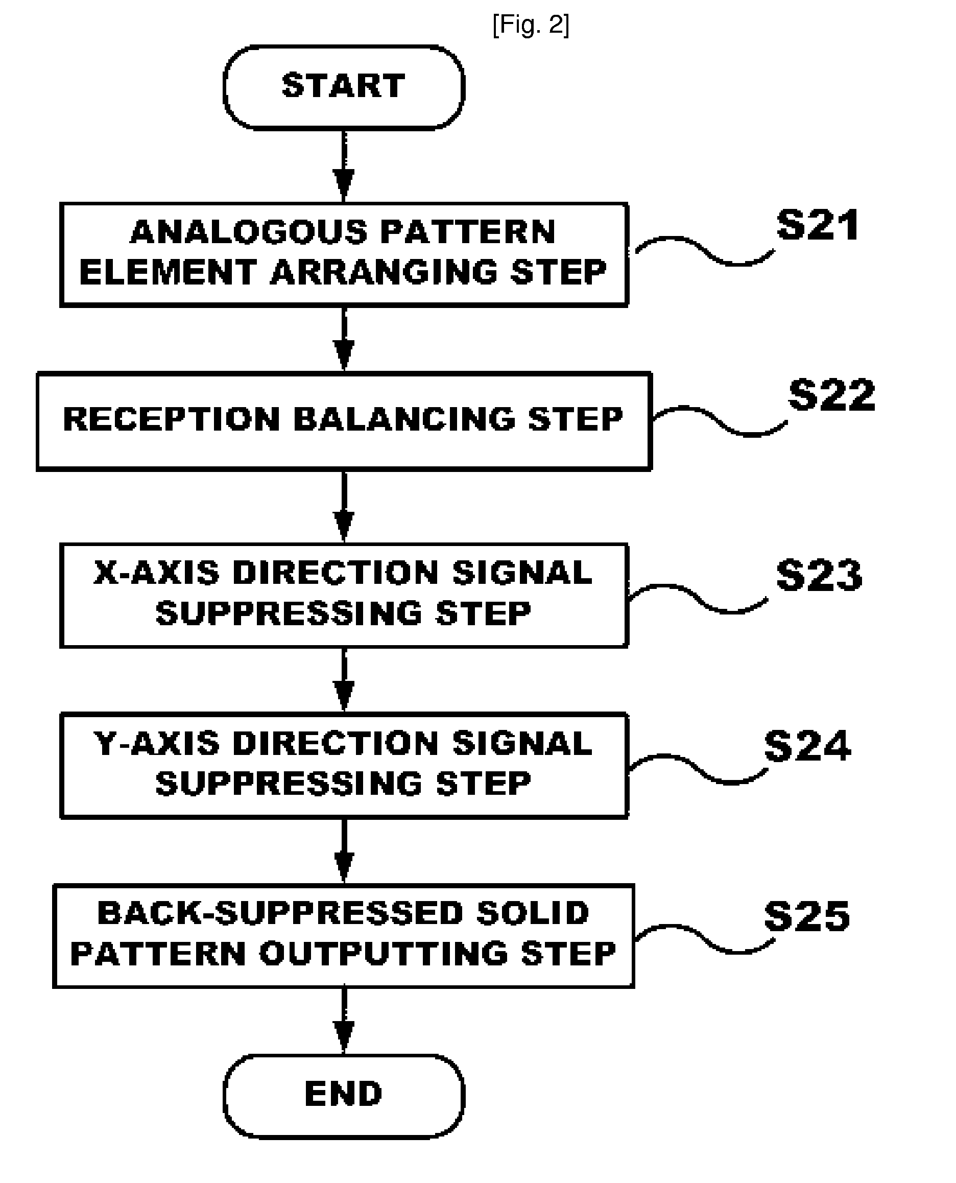
[0025]FIG. 2 is a flow chart illustrating a method for designing an array antenna for suppressing the back signal according to the present invention. As shown in FIG. 2, the method for designing the array antenna includes an analogous pattern element arranging step S21, a reception balancing step S22, an x-axis direction signal suppressing step S23, a y-axis dire...


PUM


Abstract

The present invention provides a method for designing a front directional array antenna for suppressing a back signal used in a wireless communication, comprising: (a) an analogous pattern element arranging step for arranging, on a reflecting panel which is a conductor at a predetermined interval, elements having mutual analogous emission pattern characteristic for a short axis (x axis) in which the number of arrangements is small and for a long axis (y axis) which is a perpendicular direction to the x axis; (b) a reception balancing step for forming, in the edge of the reflecting panel, reflecting surfaces having a predetermined angle and length which are symmetric centering on the front surface to direction of electric wave arrived to the elements located in the edge; (c) an x-axis direction signal suppressing step, by x-axis series distribution and synthesis, for performing as many series distribution and synthesis suppressing transfer characteristic in an x-axis direction as the number of y rows, for output distribution and synthesis for the x axis arrangement, in synthesizing a signal of the array antenna after the step (b); (d) a y-axis direction signal suppressing step, by y-axis series distribution and synthesis, for performing series distribution and synthesis suppressing transfer characteristic in a y-axis direction in finally performing distribution and synthesis in the y-axis direction, for output distribution and synthesis for the x axis arrangement; and (e) a back-suppressed sold pattern outputting step for providing result of arrangement signal distribution and synthesis of the y axis to a contact means outside the antenna device.

Description

CROSS-REFERENCE TO RELATED APPLICATION[0001]This application is a 371 of PCT / KR05 / 01983 dated Jun. 24, 2005 and claims the benefit of Korean Patent Application No. 2004-48743, filed Jun. 28, 2004, the disclosure of which is hereby incorporated herein by reference in its entirety.BACKGROUND OF THE INVENTION[0002]1. Field of the Invention[0003]The present invention relates to a front directional antenna used in a wireless communication system and, more particularly, to an isolation antenna for making transfer characteristics of a back signal zero (0).[0004]2. Description of the Related Art[0005]A method for designing a conventional isolation antenna includes an antennal element arranging step S11, a multi-back shielding step S12, a signal synthesizing step S13, and a back-suppressed pattern outputting step S14, as shown in FIG. 1.[0006]At the antenna element arranging step S11, the antenna elements are arranged at a relatively broad interval (e.g., 0.7 to 1.5 wavelength) to obtain a h...

Claims


Application Information

Patent Timeline
Patent Type & Authority Patents(United States)
IPC IPC(8): H01Q21/00H01Q3/00H01Q1/24H01Q19/10H01Q21/06H01Q21/22
CPCH01Q1/246H01Q19/106H01Q19/30H01Q21/0075H01Q21/062H01Q21/22
Inventor JEUNG, HA JAE
Owner JEUNG HA JAE
Why Eureka
Try Eureka