
Correlator and demodulation device including the correlator

a demodulation device and correlator technology, applied in amplitude demodulation, multi-frequency code system, pulse technique, etc., can solve the problems of inability to take timing shifts or timings, small correlation values, and deterioration of reception characteristics, so as to improve reception characteristics, the effect of reducing the number of errors

Active Publication Date: 2012-02-23
LAPIS SEMICON CO LTD
View PDF3 Cites 2 Cited by
  • Summary
  • Abstract
  • Description
  • Claims
  • Application Information

AI Technical Summary

Benefits of technology

[0016]The present invention provides a correlator and a demodulation device including the correlator that may suppress time synchronization instability and reception characteristic deterioration even under multipath propagation circumstances where the incoming time difference is large and the level difference is small.
[0018]That is, according to the first aspect of the invention, the first aspect employs a correlator that has n number of arithmetic circuits for obtaining autocorrelations, delays the input timings of the input signals, generates n number of autocorrelations whose times are delayed, and combines these. Accordingly, the first aspect of the invention may alleviate, in a receiver having a synchronization function of determining time synchronization on the basis of peaks of autocorrelations, time fluctuation of maximum peaks in multipath circumstances, where the incoming time difference is large, the power ratio is small, and reception becomes difficult. Thus, the first aspect of the invention may improve the reception characteristic.
[0025]According to the above aspects of the invention, the delay times of the delay OFDM signals, the gains of the gain adjustment sections, and the band characteristic of the filter circuit can be overall optimally controlled in accordance with delay times and power differences in the multipath propagation channel. Consequently, the above aspects of the invention may realize further time synchronization stabilization, and may obtain a higher reception characteristic.
[0028]According to the eighth aspect of the invention, circuit size may be reduced and consumed power may also be reduced.
[0031]That is, the tenth aspect of the invention employs a demodulation device including the correlator. Accordingly, the tenth aspect of the invention may alleviate, in a receiver having a synchronization function of determining time synchronization on the basis of peaks of autocorrelations, time fluctuation of maximum peaks in multipath circumstances, where the incoming time difference is large, the power ratio is small, and reception becomes difficult. Thus, the tenth aspect of the invention may improve the reception characteristic.
[0032]As described above, according to the above aspects of the present invention, time synchronization instability may be suppressed and reception characteristic deterioration may be alleviated even under multipath propagation circumstances, where the incoming time difference is large and the level difference is small.

Problems solved by technology

However, in a case where the received power is weak, or in a case where the influence of phasing and multipath is strong, or in a case where a narrowband noise signal has entered the reception band, sometimes the correlation value becomes small and the timing shifts or the timing becomes unable to be taken and the reception characteristic deteriorates.
That is, with the conventional correlation output, the timing cannot be detected well because the correlation value becomes high the most in the time position of the main incoming path at the time of reception of only one path.
For this reason, in conventional correlation output, time synchronization become unstable, inter-symbol interference arises, and the reception characteristic ends up deteriorating.
However, particularly under multipath propagation circumstances where the incoming time difference is large and the level difference is small, the effect is insufficient even with the technology disclosed in JP-A No. 2009-55204.

Method used


Image

  • Correlator and demodulation device including the correlator
  • Correlator and demodulation device including the correlator
  • Correlator and demodulation device including the correlator

Examples


first exemplary embodiment

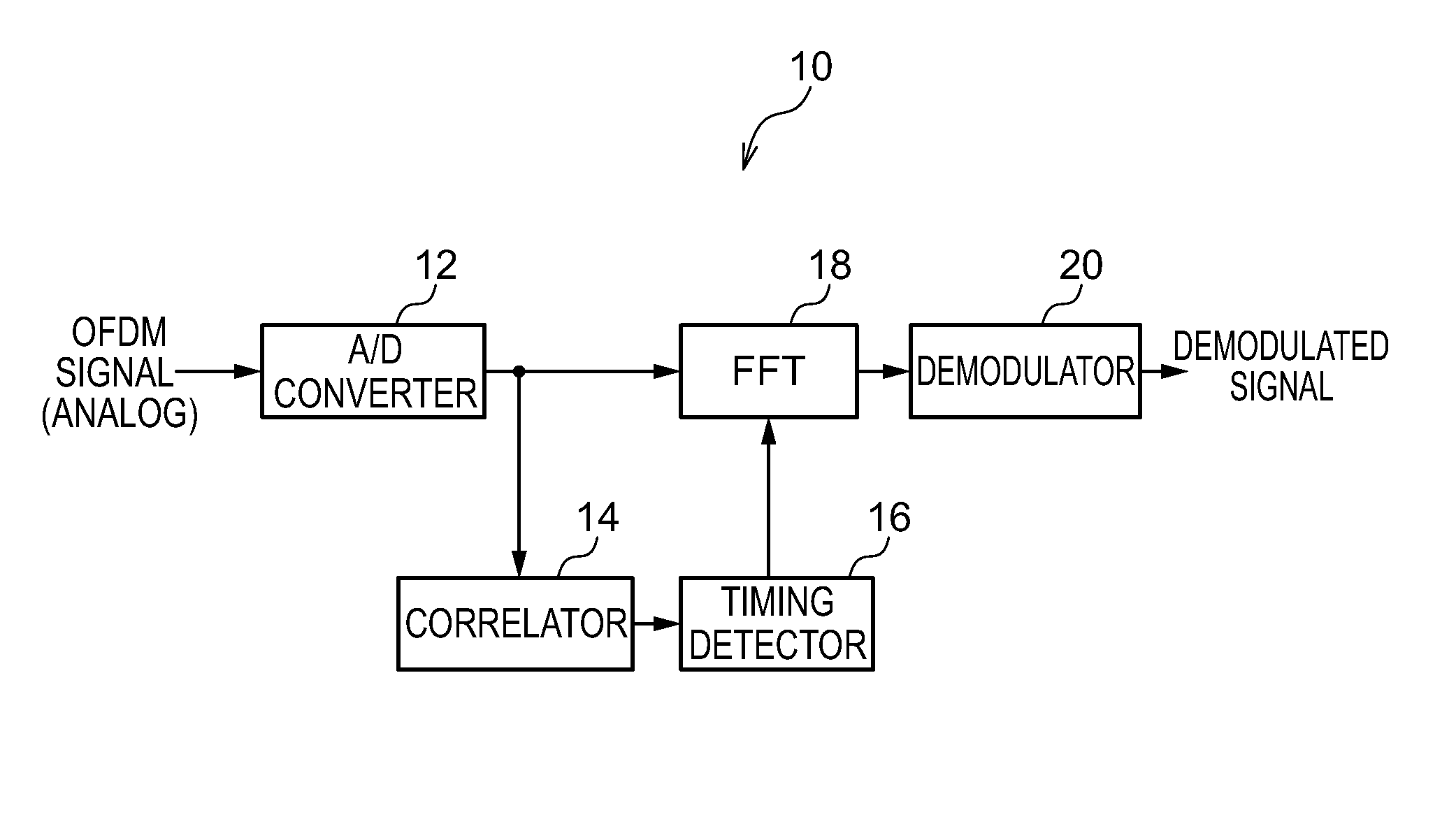
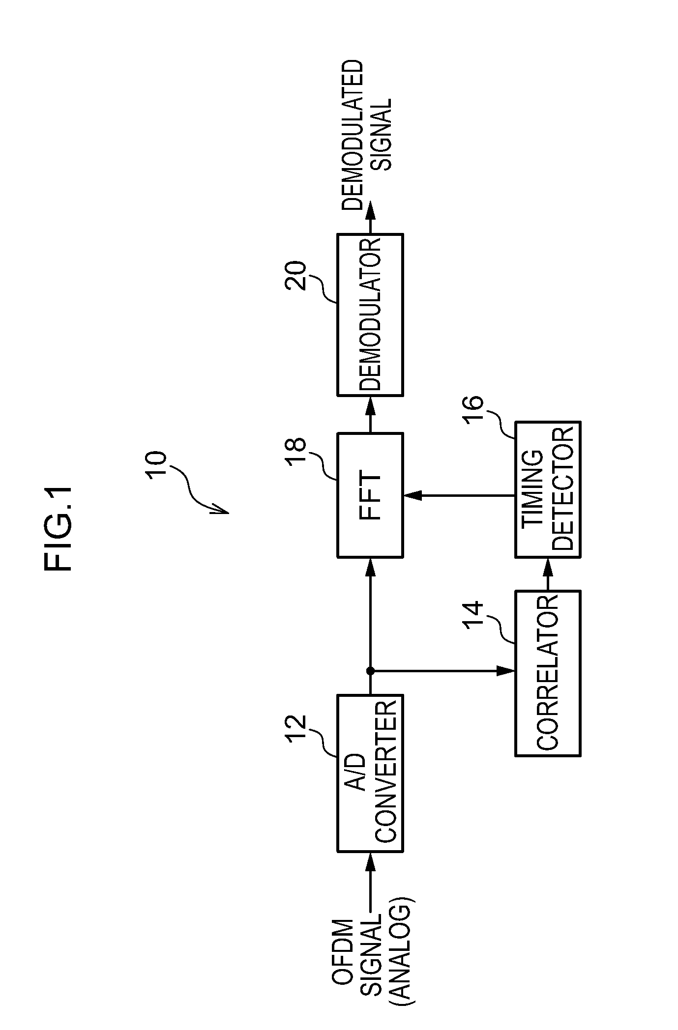
[0044]FIG. 1 is a schematic configuration diagram of an orthogonal frequency division multiplexing (OFDM) signal demodulation device 10 according to a first exemplary embodiment of the present invention. The OFDM signal demodulation device 10 is a device that receives and demodulates an OFDM signal. As shown in FIG. 7, the OFDM signal is a signal where one symbol period includes an effective symbol period and a guard interval in which part of the signal of the effective symbol period has been copied. The signal of the effective symbol period excluding the guard interval is extracted from this OFDM signal, Fourier transform is performed on the signal of the effective symbol period (effective symbol signal), and the effective symbol signal is demodulated.

[0045]As shown in FIG. 1, the OFDM signal demodulation device 10 is equipped with an A / D converter 12, a correlator 14, a timing detector 16, a fast Fourier transformer (FFT) 18, and a demodulator 20.

[0046]The A / D converter 12 samples...

second exemplary embodiment

[0071]In the present exemplary embodiment, an example where the correlator is equipped with a write processing circuit, a memory, and a read-out processing circuit, instead of the delay circuits of the first exemplary embodiment, will be described.

[0072]FIG. 5 is a diagram showing the configuration of a correlator 36 of the present exemplary embodiment. The configuration of the OFDM demodulation device 10 is the same as in the first exemplary embodiment, except that the correlator 14 is replaced by the correlator 36, and therefore detailed description will be omitted.

[0073]As shown in FIG. 5, the correlator 36 of the present exemplary embodiment is disposed with a write processing circuit 38, a random access memory (RAM) 40, and a read-out processing circuit 42, instead of the delay circuits 22 of the correlator 14 of the first exemplary embodiment, and is further equipped with a control circuit 44.

[0074]The present exemplary embodiment employs a memory, instead of the delay circuit...

third exemplary embodiment

[0081]In the present exemplary embodiment, an example in which the example of the second exemplary embodiment is generalized will be described.

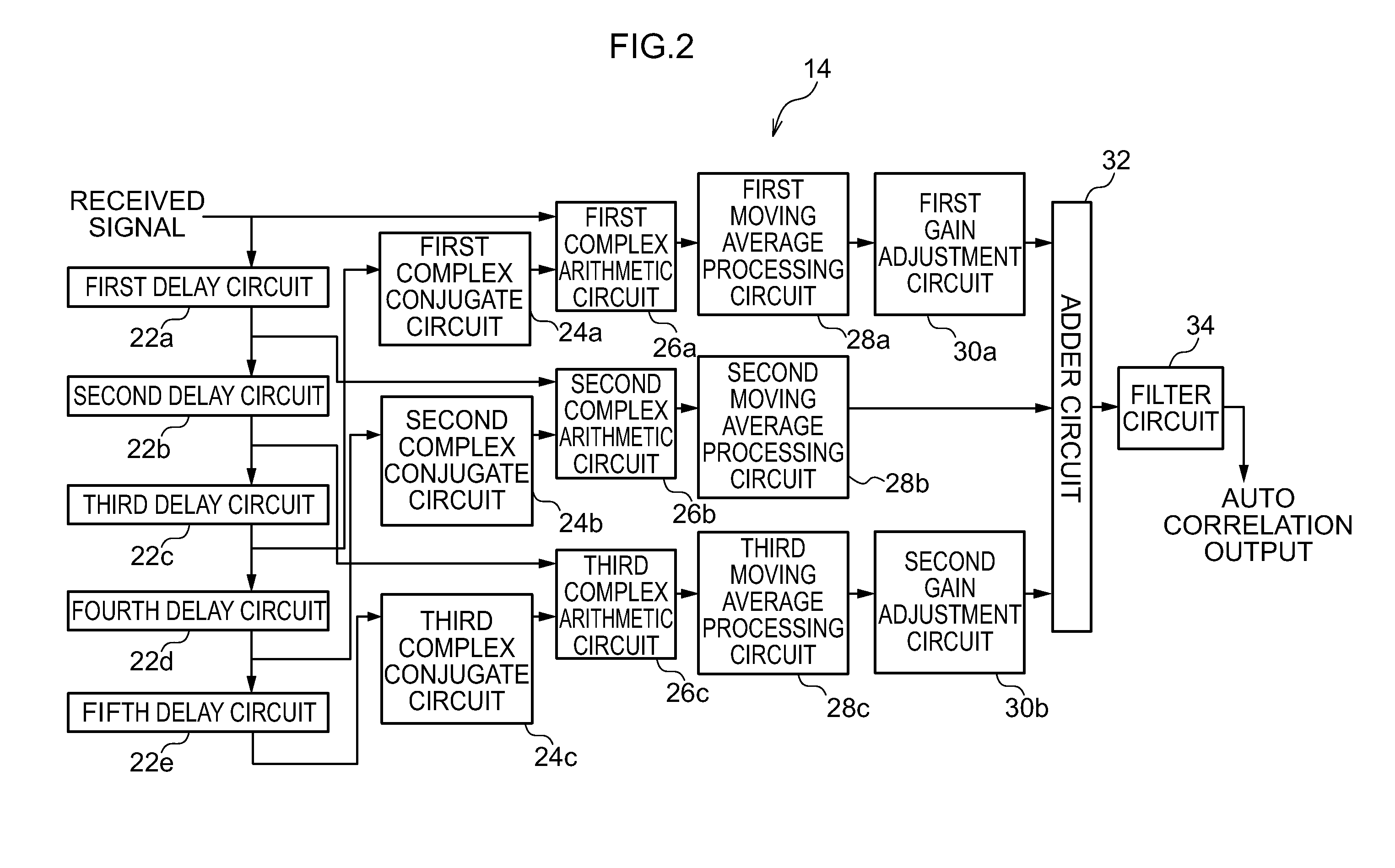
[0082]That is, in the second exemplary embodiment, there were three each of the complex conjugate circuits 24, the complex arithmetic circuits 26, and the moving average processing circuits 28. However, in the present exemplary embodiment, as shown in FIG. 6, the number of each of those may be changed to n number equal to or greater than three. Further, in the present exemplary embodiment, the number of the gain adjustment circuits 30 may also be changed to n number equal to or greater than three, in correspondence to the number of each of those.

[0083]In accompaniment with this, the signal data are read out from the RAM 40 at 2n−1 number of delay timings by the control circuit 44, and are sent to the second to nth complex arithmetic circuits 26 and the first to nth complex conjugate circuits 24. Further, the adder circuit 32 adds and combines...


PUM


Abstract

The Present invention provides a correlator including, a read-out processing circuit that reads out an OFDM signal in RAM as 2n−1 number of delay OFDM signals that are increased and delayed sequentially with their adjusted read-out timings. Complex conjugate circuits that outputs complex conjugates of the inputted nth to 2n−1th delay OFDM signals. Complex arithmetic circuits that perform complex multiplication to inputted original OFDM signal, the first to n−1th delay OFDM signals, and the output signals from the complex conjugate circuits. Moving average processing circuits take the moving average of the GI length, gain adjustment circuits adjust the gains, an adder circuit adds the outputs of the adjustment circuits, and a filter circuit smoothes the addition result. A control circuit variably controls the delay of the delay OFDM signals, the gains of the gain adjustment circuits, and the band characteristic of the filter circuit.

Description

CROSS-REFERENCE TO RELATED APPLICATION[0001]This application claims priority under 35 USC 119 from Japanese Patent Application No. 2010-183291, filed on Aug. 18, 2010, the disclosure of which is incorporated by reference herein.BACKGROUND OF THE INVENTION[0002]1. Field of the Invention[0003]The present invention relates to a correlator that determines the correlation between an OFDM signal, which has an effective symbol period and a guard interval in which part of the effective symbol signal has been copied, and a delay signal obtained by delaying the OFDM signal. The present invention also relates to a demodulation device that includes the correlator. In particular, the present invention relates to a correlator and a demodulation device including the correlator that can also cope with multipath propagation circumstances where the incoming time difference is large and the level difference (power ratio) is small.[0004]2. Description of the Related Art[0005]In recent years, the orthog...

Claims


Application Information

Patent Timeline
IPC IPC(8): H04K1/10H04L27/06
CPCH04L27/2663H04L27/2688H04L27/2678H04L27/2671
Inventor AKAHORI, HIROJI
Owner LAPIS SEMICON CO LTD
Learn More