Electric power steering apparatus
- Summary
- Abstract
- Description
- Claims
- Application Information
AI Technical Summary
Benefits of technology
Problems solved by technology
Method used
Image

Examples
first embodiment
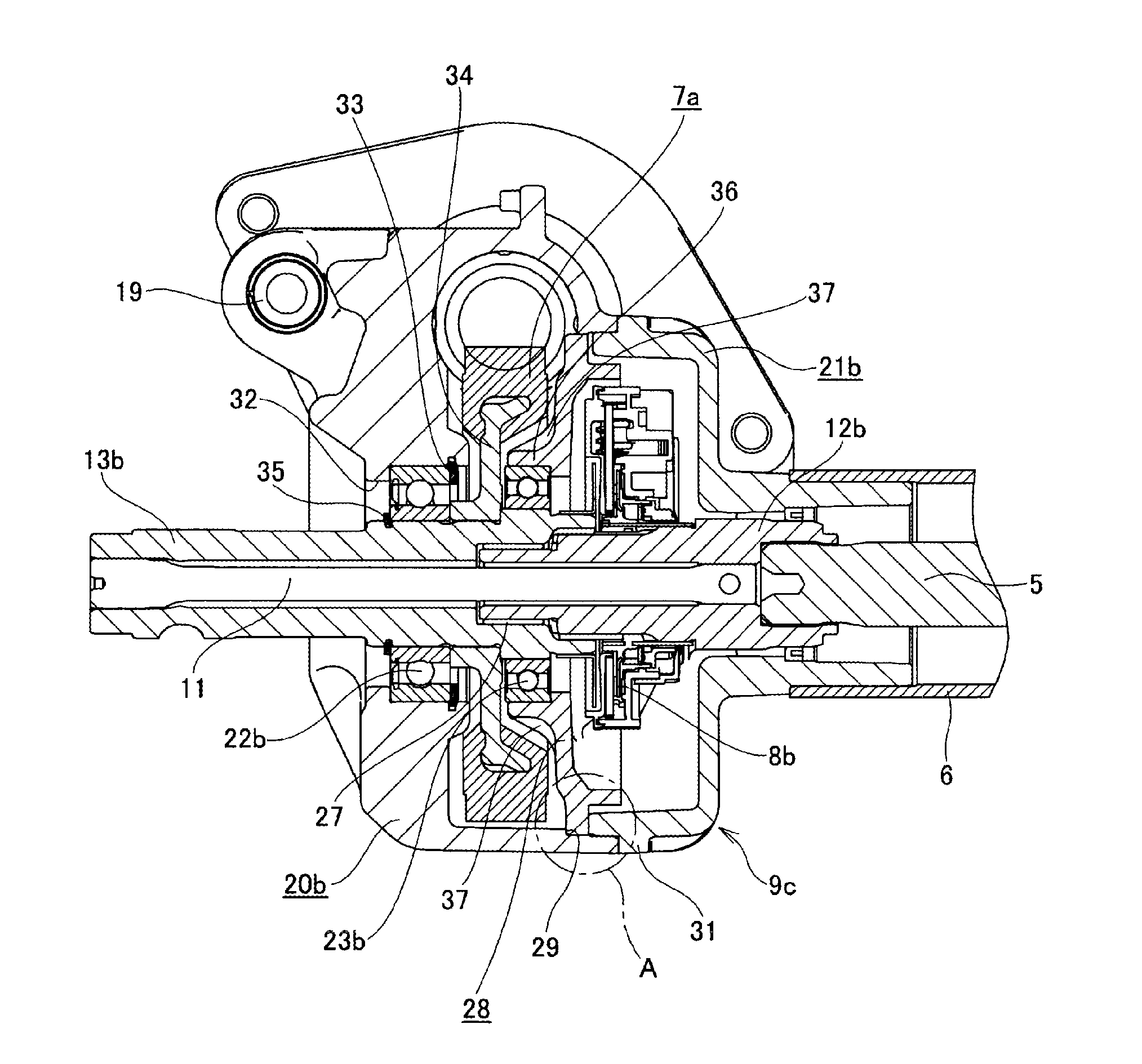
[0049]FIGS. 1 to 6 show an electric power steering apparatus according to the invention. The electric power steering apparatus has an input shaft 12b, an output shaft 13b and a housing 9 that rotatably supports the input shaft 12b and the output shaft 13b. The housing 9 is configured by combining a gear housing 20b and a housing cover 21b. Each of the gear housing 20b and the housing cover 21b is formed by a die-casting molding using an aluminum alloy or injection molding using a high-functional resin, for example. The input shaft 12b and the output shaft 13b are formed to have a hollow circular tube shape and are connected by a torsion bar 11 with being concentrically arranged. That is, front and rear end portions of the torsion bar 11 are respectively connected to a front end portion of the output shaft 13b and a rear end portion of the input shaft 12b. The output shaft 13b is coupled to an input shaft 3 (see FIG. 15) of a steering gear unit 2 via universal joints 15a, 15b and an ...
third embodiment
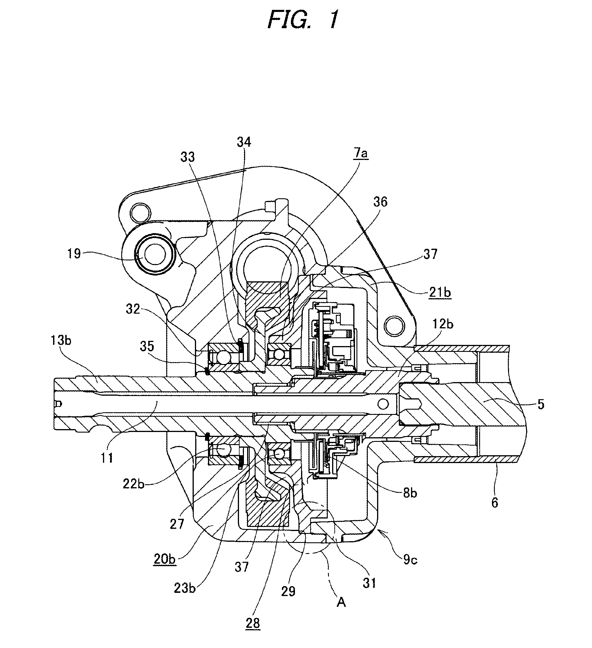
[0072]FIGS. 8 and 9 show the invention. In the electric power steering apparatus of this example, the intermediate plate 28, which is made in the same manner as the gear housing 20b and the housing cover 21b, is press-fitted and fixed in the housing 9c by the interference fit. A portion of the intermediate portion of the output shaft 13b near the rear end is supported using the intermediate plate 28. In this example, in order to press-fit and fix the intermediate plate 28 at a predetermined position in the housing 9c, a portion of the inner peripheral surface of the gear housing 20b near the rear end opening is provided with the rearwardly facing step surface 29. A rear-side part of the step surface 29 of the inner peripheral surface of the gear housing 20b has a cylindrical shape having a step at which a small diameter portion 45 near the step surface 29 and a large diameter portion 46 of an opening-side far from the step surface 29 are made to continue by a small step part. An out...
fifth embodiment
[0078]FIGS. 11 and 12 show the invention. In this example, a ridge 50 having a triangular sectional shape and a width in the radial direction reducing towards the distal end thereof is formed on a rear surface outer peripheral portion of the intermediate plate 28a over an entire circumference thereof. During the process of connecting and fixing the gear housing 20b and the housing cover 21b, the front end surface of the housing cover 21b is butted to the rear surface outer peripheral portion of the intermediate plate 28a, while flattening the ridge 50 by the front end surface of the housing cover 21b.
PUM
 Abstract
Description
Claims
Application Information