Hot water-centered combined hot water and heating boiler

Active Publication Date: 2015-10-22
KYUNGDONG NAVIEN
View PDF21 Cites 29 Cited by
  • Summary
  • Abstract
  • Description
  • Claims
  • Application Information

AI Technical Summary

Benefits of technology

[0020]According to the hot water-centered hot water and heating combination boiler, since the combustion gas of the burner is directly heat-exchanged with the cold water in the main heat exchanger to supply the hot water, the hot water desire

Problems solved by technology

However, since the cold water is indirectly heated in the hot-water supply heat exchanger 40, it takes a lot of time until the temperature of the hot water reaches a preset temperature desired b

Method used


Image

  • Hot water-centered combined hot water and heating boiler
  • Hot water-centered combined hot water and heating boiler
  • Hot water-centered combined hot water and heating boiler

Examples


first embodiment

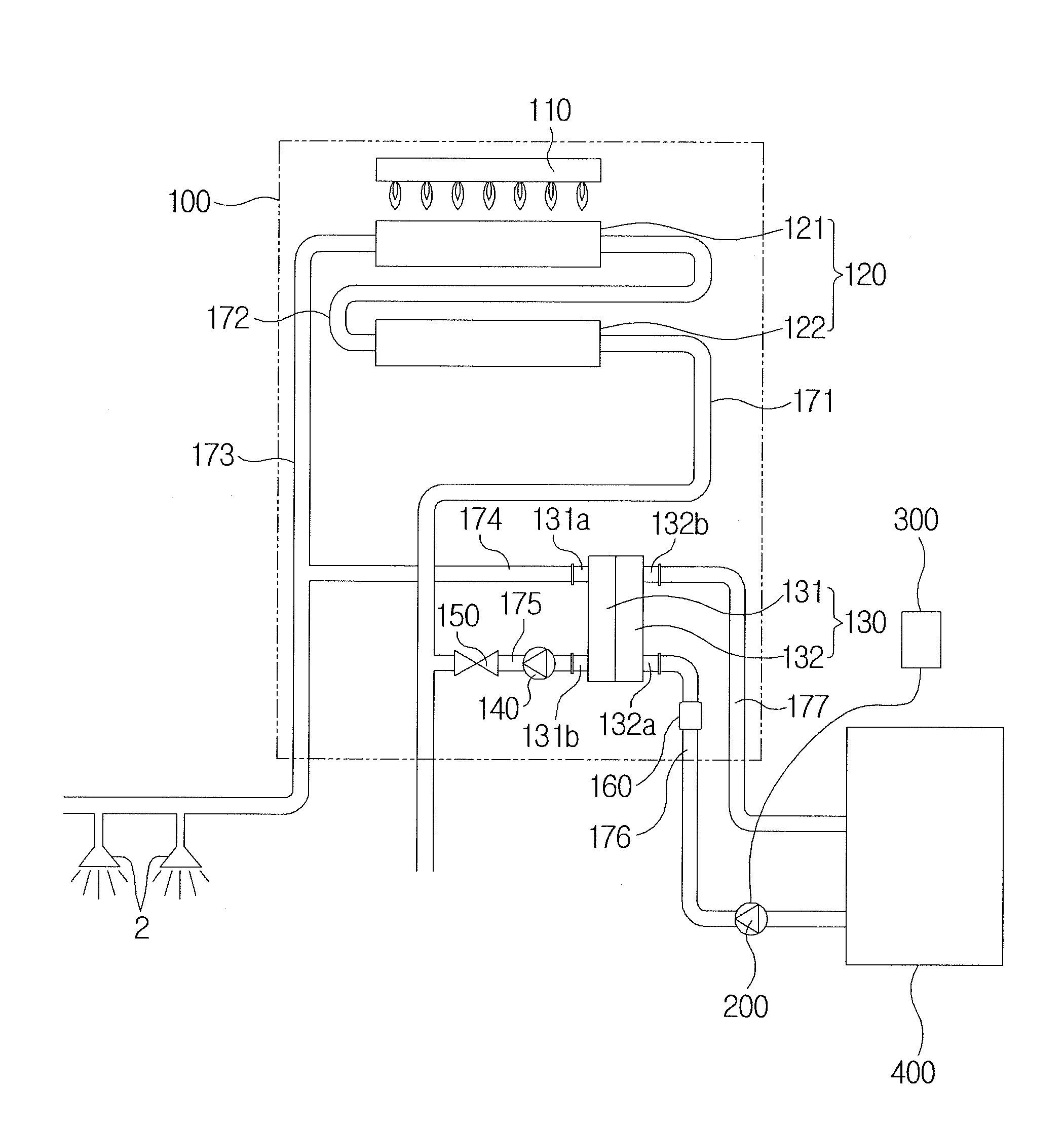
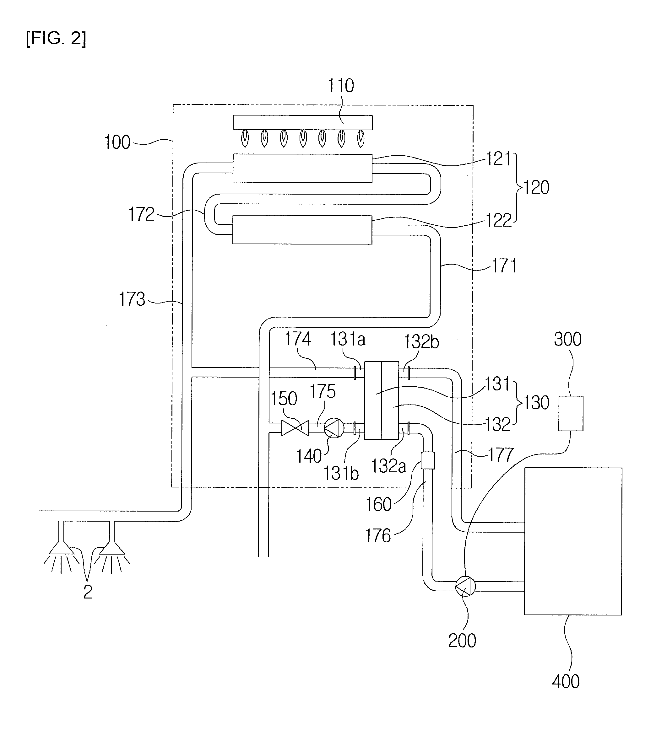
[0029]FIG. 2 is a view of a boiler according to a first embodiment of the present invention.

[0030]A hot water and heating combination boiler 100 according to the first embodiment includes a burner 110 for burning a mixed gas in which air is mixed with gas to generate flames, a main heat exchanger 120 directly heating cold water by combustion heat of the burner 110, and an auxiliary heat exchanger 130 for heat-exchanging the water heated in the main heat exchanger 120 with water returning from a heating consumption place in order to supply heating water having a high temperature.

[0031]The main heat exchanger 120 is constituted by a sensible heat heat-exchanger 121 that absorbs combustion sensible heat of the burner 110 and a latent heat heat-exchanger 122 that absorbs latent heat of vapor contained in combustion gas that is heat-exchanged in the sensible heat heat-exchanger 121.

[0032]In the current embodiment, although the burner 110 is a downward combustion type burner, the burner m...

second embodiment

[0056]FIG. 5 is a view of a boiler according to a second embodiment of the present invention. Since most of the components of the boiler according to the second embodiment are the same as that of the first embodiment, hereinafter, different components will be mainly described.

[0057]A hot water and heating combination boiler 100-1 according to the second embodiment includes a burner 110, a main heat exchanger 120-1 directly heating cold water by combustion heat of the burner 110, and an auxiliary heat exchanger 130 for heat-exchanging water heated in the main heat exchanger 120-1 with returning water to supply the returning water having a high temperature.

[0058]The main heat exchanger 120-1 is constituted by a sensible heat heat-exchanger 121-1 and latent heat heat-exchangers 122-1 and 123-1. In the current embodiment, the latent heat heat-exchangers 122-1 and 123-1 are constituted by a hot water latent heat heat-exchanger 122-1 having one side that is connected to a cold water inflo...


PUM


Abstract

The objective of the present invention is to provide a hot water-centered hot water and heating combination boiler, in which heat exchange for a hot water supply is performed in a main heat exchanger and heat exchange for a heating water supply is performed in an auxiliary heat exchanger so that the hot water supply can be accelerated, energy can be saved, and the temperature of the hot water can be controlled with ease. To achieve the abovementioned objective, the boiler of the present invention includes: a cold water inflow tube through which cold water flows in; a main heat exchanger which heats the cold water flowing in through the cold water inflow tube by using the combustion heat of a burner; a hot water discharge tube which discharges the hot water heated in the main heat exchanger; an auxiliary heat exchanger which supplies heating water during a heating mode, in which heating consumption place, and causes heat exchange to occur between the heated water in the main heat exchanger and the lowered temperature returning water, in which the heating consumption place; and a control part which controls the combustion of the burner during a hot water mode and heating mode.

Description

TECHNICAL FIELD[0001]The present invention relates to a hot water-centered hot water and heating combination boiler, and more particularly, to a hot water-centered hot water and heating combination boiler in which cold water is directly heated in a main heat exchanger by combustion heat of a burner to supply hot water in a hot water mode, and water returning from a heating consumption place is indirectly heated in an auxiliary heat exchanger by using the water heated in the main heat exchanger to supply heating water in a heating mode.BACKGROUND ART[0002]Boilers are being used for providing heating or hot water in general homes or public buildings. Commonly, boilers use oil or gas as fuels to burn the oil or gas through burners and then heat water by using combustion heat generated during the combustion process to circulate the heated water to indoor spaces, thereby heating the indoor spaces or providing hot water as necessary.[0003]FIG. 1 is a view of a heating and hot water boiler...

Claims


Application Information

Patent Timeline
IPC IPC(8): F24D19/10F24D3/08F24H8/00F24D17/00F24H1/14F24H1/52
CPCF24D19/1069F24H1/14F24D3/08F24H8/00F24D17/0031F24H1/52F24H1/523F24H9/2035F24H1/12F24H9/00F24H9/20Y02B30/00F24H15/238F24H15/36
Inventor PARK, JUN KYUKIM, HYOUNG RAE
Owner KYUNGDONG NAVIEN
Why Eureka
Try Eureka