Wideband deformed dipole antenna for LTE and GPS bands

a dipole antenna and wideband technology, applied in the field of antennas, can solve the problems of difficult to achieve such wideband application in a single antenna, limited protocol of early 2g/3g communication technologies, and increased potential impact of detuning effects, so as to reduce assembly failure rates, increase antenna bandwidth, and reduce interference from the attached cable

a dipole antenna and wideband technology, applied in the field of antennas, can solve the problems of difficult to achieve such wideband application in a single antenna, limited protocol of early 2g/3g communication technologies, and increased potential impact of detuning effects, so as to reduce assembly failure rates, increase antenna bandwidth, and reduce interference from the attached cable

US20150303579A1Active Publication Date: 2015-10-22TAOGLAS GROUP HLDG

Image

  • Wideband deformed dipole antenna for LTE and GPS bands
  • Wideband deformed dipole antenna for LTE and GPS bands
  • Wideband deformed dipole antenna for LTE and GPS bands

Examples


example

[0024]Now turning to the drawings:

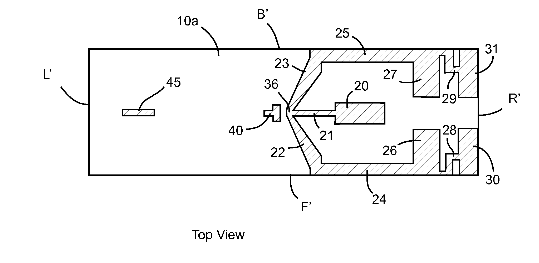
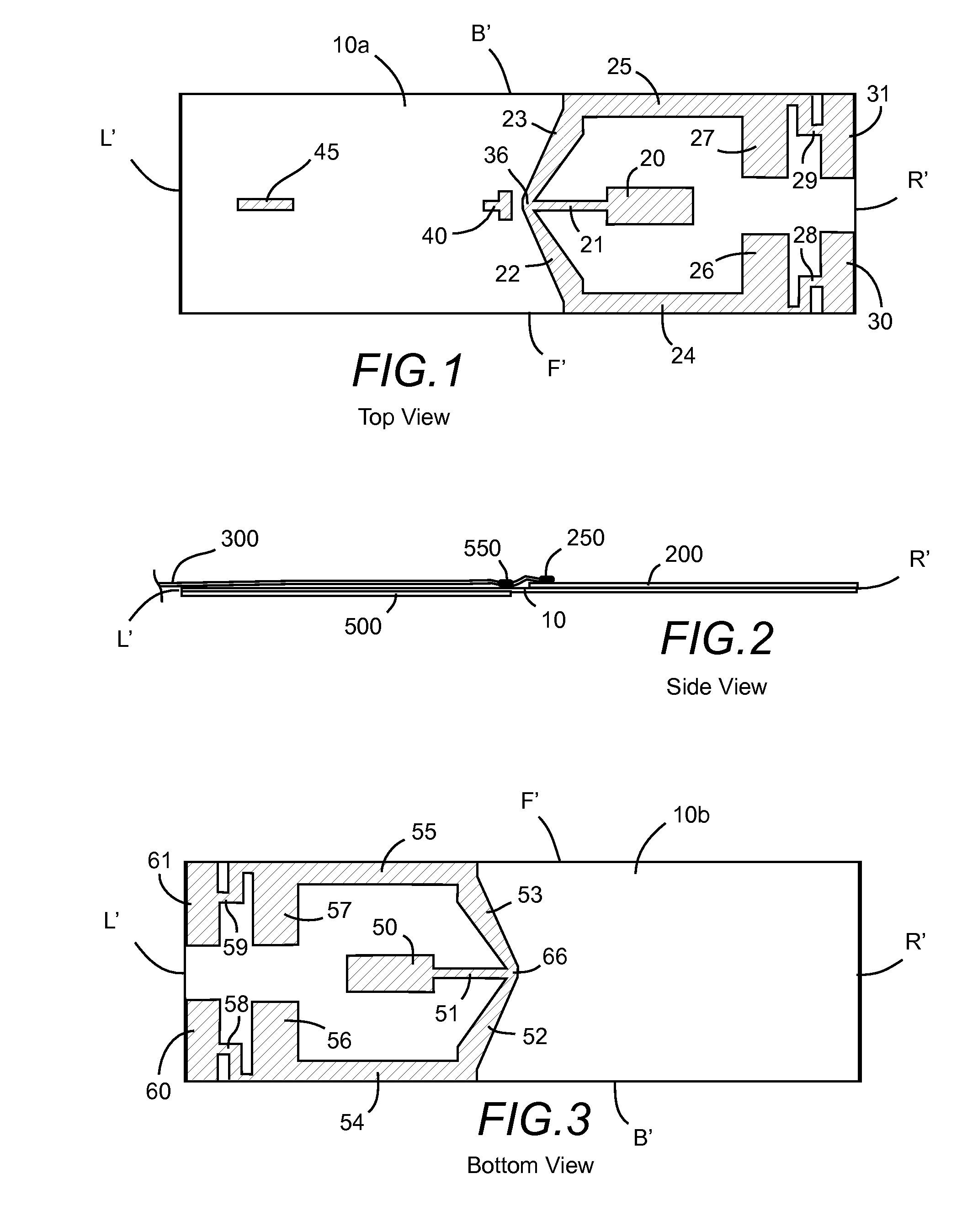
[0025]FIG. 1 shows a top view of a wideband LTE and GPS deform dipole antenna and associated trace elements.

[0026]A first dipole conductor is printed or otherwise disposed on a top right side surface of a circuit board 10a.

[0027]The first dipole conductor comprises a first apex 36 positioned near a center of the circuit board. A first arm section 22 extends from the first apex toward a front side peripheral edge F′, or periphery. A first L-shaped section 24 extends from the first arm section to a first L-shaped stub 26 along the front peripheral edge. A first H-shaped section 28 extends from the first L-shaped stub to a first H-shaped stub 30.

[0028]The first dipole conductor further comprises a second arm section 23 extending from the first apex toward a rear side peripheral edge B′, or periphery. A second L-shaped section 25 extends from the second arm section to a second L-shaped stub 27 along the rear peripheral edge. A second H-shaped section 2...


PUM


Abstract

A deformed dipole is suggested with trace elements configured for wideband LTE and GPS operation. The deformed dipole comprises a first dipole conductor disposed on a first surface and first side of the circuit board and a second dipole conductor disposed on an opposite surface and opposite side of the circuit board.

Description

TECHNICAL FIELD[0001]This invention relates to antennas; and more particularly, to a wideband deformed dipole antenna having two parallel opposing sections and configured for LTE and GPS bands.BACKGROUND ART[0002]Long Tern Evolution (LTE) communication technology is becoming increasingly popular. Earlier 2G / 3G communication technologies are limited by protocol. LTE technologies are improving application speeds significantly. Currently, an increasing number of high tech electronic devices are being designed to function over LTE bands.[0003]Antennas in LTE capable devices are a critical component because the LTE operation bandwidth is widespread, giving rise to greater potential impact from detuning effects. Achieving such wideband application in a single antenna is a difficult objective.[0004]Modern electronic devices can benefit from a resonant trace for global positioning system (GPS) bands.SUMMARYTechnical Problem[0005]There is a need for an antenna configured for multiple resonan...

Claims


Application Information

Patent Timeline
22 Oct 2015
Publication
US20150303579A1
IPC
H01Q9/20; H01Q1/38
CPC
H01Q1/38; H01Q9/20; H01Q13/04; H01Q9/28; H01Q5/364; H01Q9/285; H01Q5/371
Inventors
YANG, WAYNE; QUINLAN, RONAN