Methods, systems and components for multi-storey building construction

a multi-storey building and building technology, applied in the direction of building components, portable lifting, construction materials, etc., can solve the problems of high labor intensity, inherently slow overall process, and high-pressure concrete pumping equipment requirements, and achieve the effect of facilitating the erection of wall sections

Inactive Publication Date: 2015-10-29
MERHIS
View PDF15 Cites 25 Cited by
  • Summary
  • Abstract
  • Description
  • Claims
  • Application Information

AI Technical Summary

Benefits of technology

[0069]In one preferred embodiment, the carriage assembly is motorised, incorporating a first drive mechanism adapted to drive the carriage on the rail, optionally by remote control. Preferably, the carriage assembly includes a second drive mechanism adapted in use to progressively raise and lower the suspended panel via the engagement mechanism, again optionally by remote control. Preferably, the second drive mechanism is connected with a winch, adapted to control the wire rope connected to the panel and hence to regulate the height of the panel.
[0070]In some embodiments, the second drive mechanism permits the panels to be raised or lowered by a distance corresponding to at least two floor levels, thereby permitting the same rail formation to facilitate the erection of wall sections on multiple levels of the building structure.

Problems solved by technology

Although this construction technique has proven to be relatively effective and reliable, it suffers from a number of significant and inherent disadvantages.
Firstly, a large number of separate trades are required on site, to implement a highly labour-intensive process involving lifting of formwork and temporary support structures into position on site, erecting the formwork, placing the steel reinforcement, pumping and pouring the concrete, screeding and levelling the wet mix, and subsequently dismantling and removing the formwork once the concrete has set.
Furthermore, in multi-story developments, sophisticated and expensive high-pressure concrete pumping equipment is required in order to deliver the wet concrete mix at the necessary elevations.
As well as the labour intensity, labour cost and planning complexity, the overall process is inherently slow.
This often necessitates delays of up to several weeks between floors, because many of the central process steps are on the same critical path, which becomes rate-limiting for the entire project.
In the context of a medium to high-rise developments, the cumulative delays inherent in this process can amount to many months, at an economic cost of many millions of dollars for a single construction project.

Method used


Image

  • Methods, systems and components for multi-storey building construction
  • Methods, systems and components for multi-storey building construction
  • Methods, systems and components for multi-storey building construction

Examples


Embodiment Construction

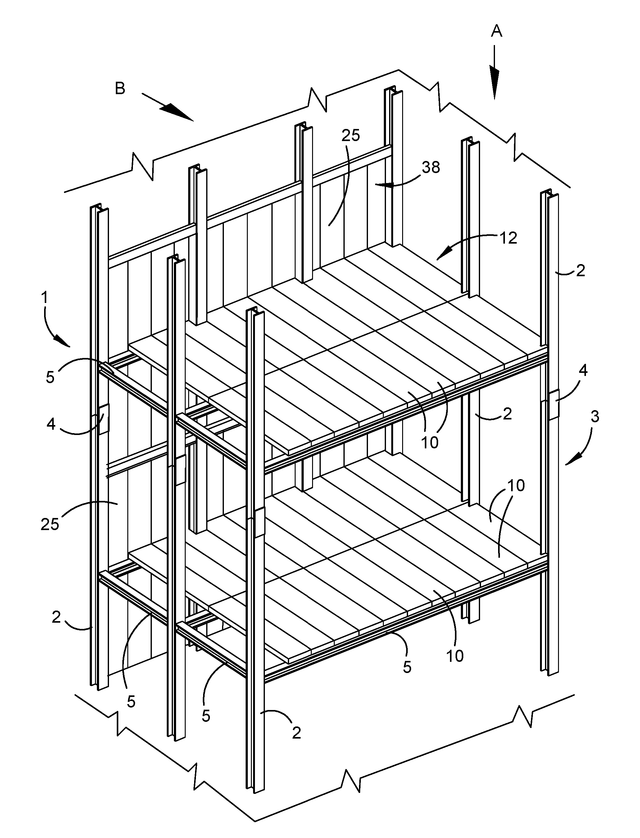
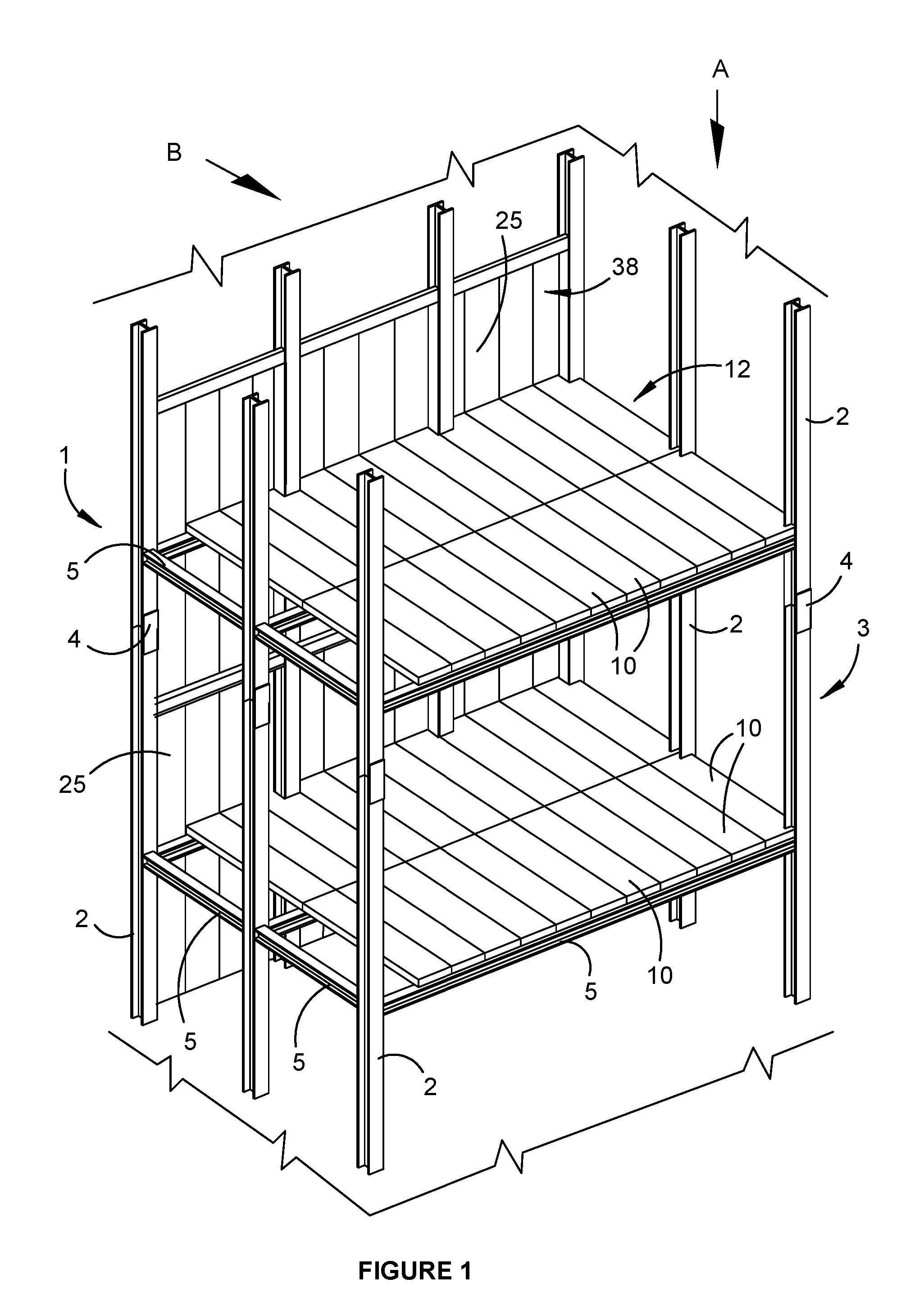
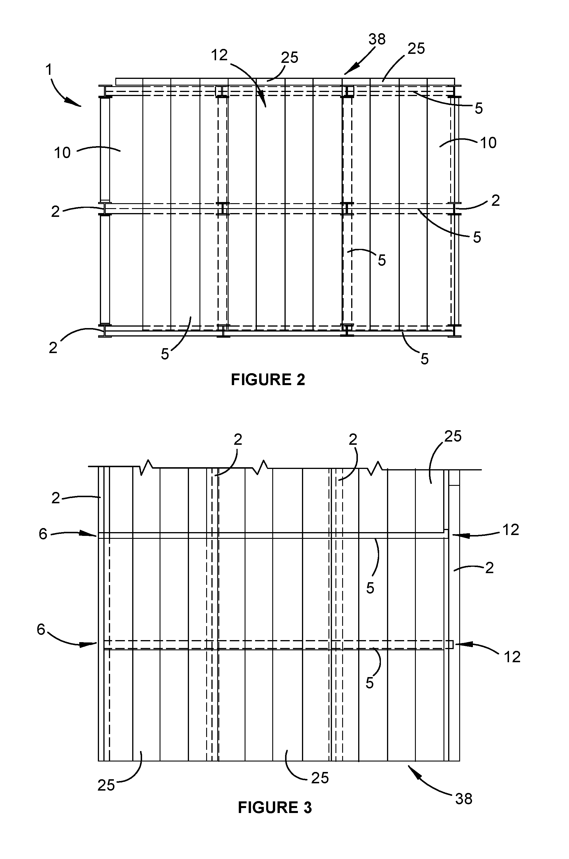
[0107]The invention in one aspect provides a multi-storey building structure 1 and an associated method of construction. Referring initially to FIGS. 1 to 3, the structure 1 includes a series of vertically oriented support columns 2 disposed in spaced apart relationship to define a generally vertical support structure 3. In this embodiment, the support columns 2 are formed from structural steel I-beams, connected end-to-end as required by means of complementary steel connection brackets 4 and associated bolts. However, it should be appreciated that other structural materials, column configurations and interconnection methods may additionally or alternatively be used.

[0108]A series of horizontally oriented floor support beams 5 are connected to the vertical support columns 2 in generally parallel spaced apart relationship, to define a horizontal support structure 6 for an elevated floor. The floor support beams 5 are preferably also formed from structural steel I-beams, bolted or wel...


PUM


Abstract

A method of forming a multi-storey building structure, comprising the steps of erecting a series of vertically oriented support columns (2) in spaced apart relationship to define a generally vertical support structure, and connecting a series of horizontally oriented support beams (5) to the support columns in spaced apart relationship to define a generally horizontal support structure for a floor. Furthermore, releasably attaching a crane carriage assembly (70) to a rail formation (63) attached to the support structure (B), whereby the carriage assembly is adapted securely to traverse the rail, and hoist, position and secure a plurality of prefabricated lightweight structural panels (10), in substantially contiguous side-by-side relationship on the horizontal support structure to form a structural floor.

Description

FIELD OF THE INVENTION[0001]The present invention relates generally to building construction, and more specifically to methods, systems and components for multi-storey building construction.[0002]The invention has been developed primarily for use in connection with multi-level residential apartment buildings, retail shopping complexes, hotels, and the like and will be described predominantly in this context. It should be appreciated, however, that the invention is not limited to this particular field of use, being potentially applicable to a broad range of other building types including high-rise office blocks, schools, hospitals, security complexes and other forms of commercial and industrial complex such as factories, hangers and warehouses, as well as bridges, towers, tunnels, elevated walkways, airport infrastructure and other civil engineering developments. It should also be understood that although the invention is particularly well adapted for multi-level constructions, it ma...

Claims


Application Information

Patent Timeline
Patent Type & Authority Applications(United States)
IPC IPC(8): E04B1/35E04B1/24E04C2/04E04B1/38E04B5/02E04G21/14E04H1/00E04B1/19
CPCE04B1/3511E04H1/00E04B1/24E04B1/19E04C2/04E04B1/3516E04B5/02E04G21/14E04B1/38E04B2/94E04B2001/2415E04B2001/2448E04B2001/2481E04B2001/2484E04B2001/2496B66D3/18E04G21/142E04G21/167E04B5/10E04C2/049E04C2002/002E04C2002/004
Inventor MERHI, MARKMERHI, KHALIL
Owner MERHIS
Why Eureka
Try Eureka