Downhole cleaning system

a cleaning system and downhole technology, applied in the direction of borehole drives, drilling accessories, borehole/well accessories, etc., can solve the problem of valve blockage, and achieve the effect of simple and easy submergen

Inactive Publication Date: 2015-10-29
WELLTEC AS
View PDF7 Cites 3 Cited by
  • Summary
  • Abstract
  • Description
  • Claims
  • Application Information

AI Technical Summary

Benefits of technology

[0004]It is an object of the present invention to wholly or partly overcome the above disadvantages and drawbacks of the prior art. More specifically, it is an object to provide a downhole cleaning system which is more simple and easier to submerge into a wellbore without using drill pipes or coiled tubing.

Problems solved by technology

However, such valves may get stuck due to precipitation of scales and other particles accumulated on the valve so that the valve is blocked.
Thus, it is sometimes necessary to clean the valves before they can be operated.
However, such coiled tubing is not always situated on the rig or vessel and therefore needs to be transported to the rig or vessel.

Method used


Image

  • Downhole cleaning system
  • Downhole cleaning system
  • Downhole cleaning system

Examples


Embodiment Construction

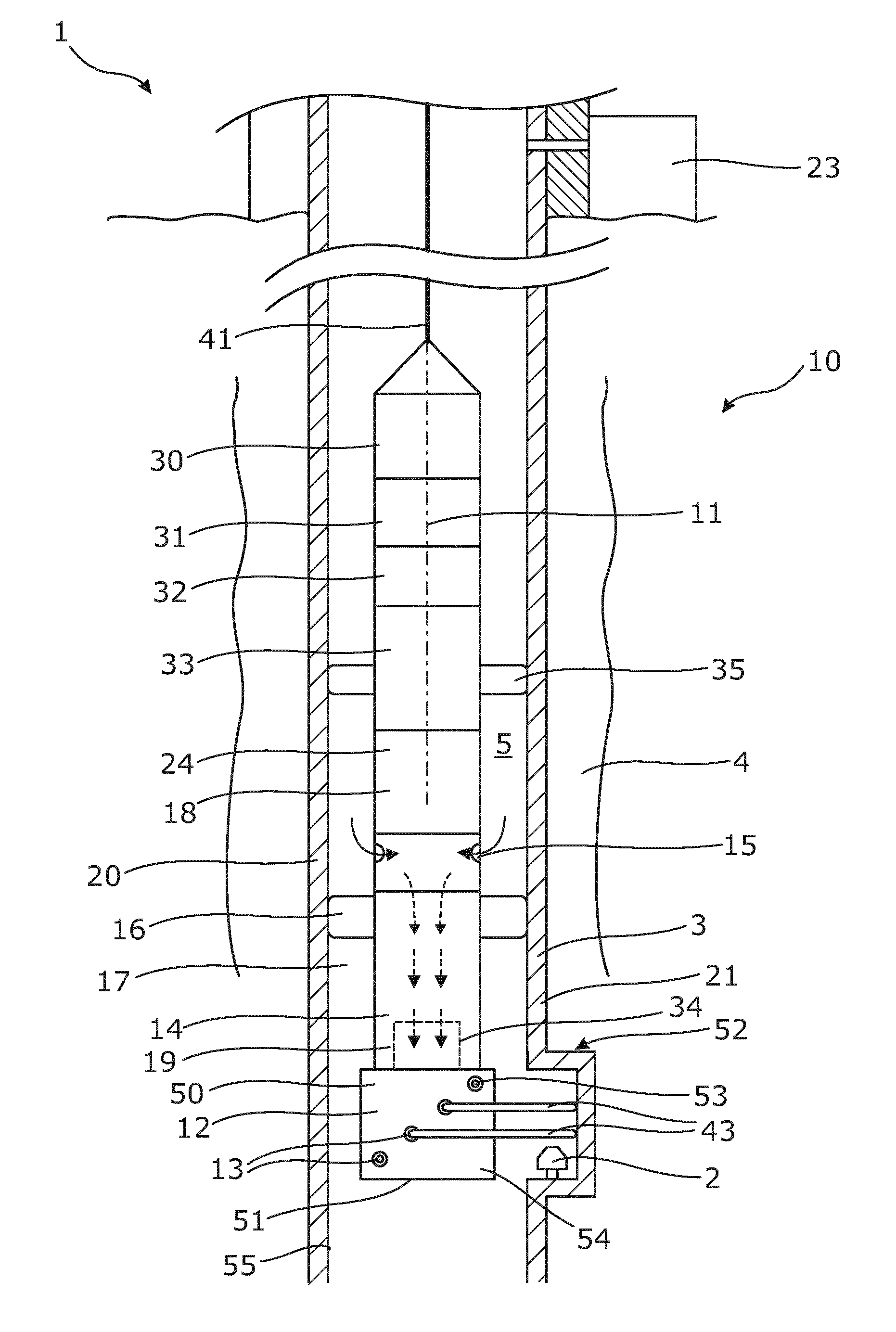
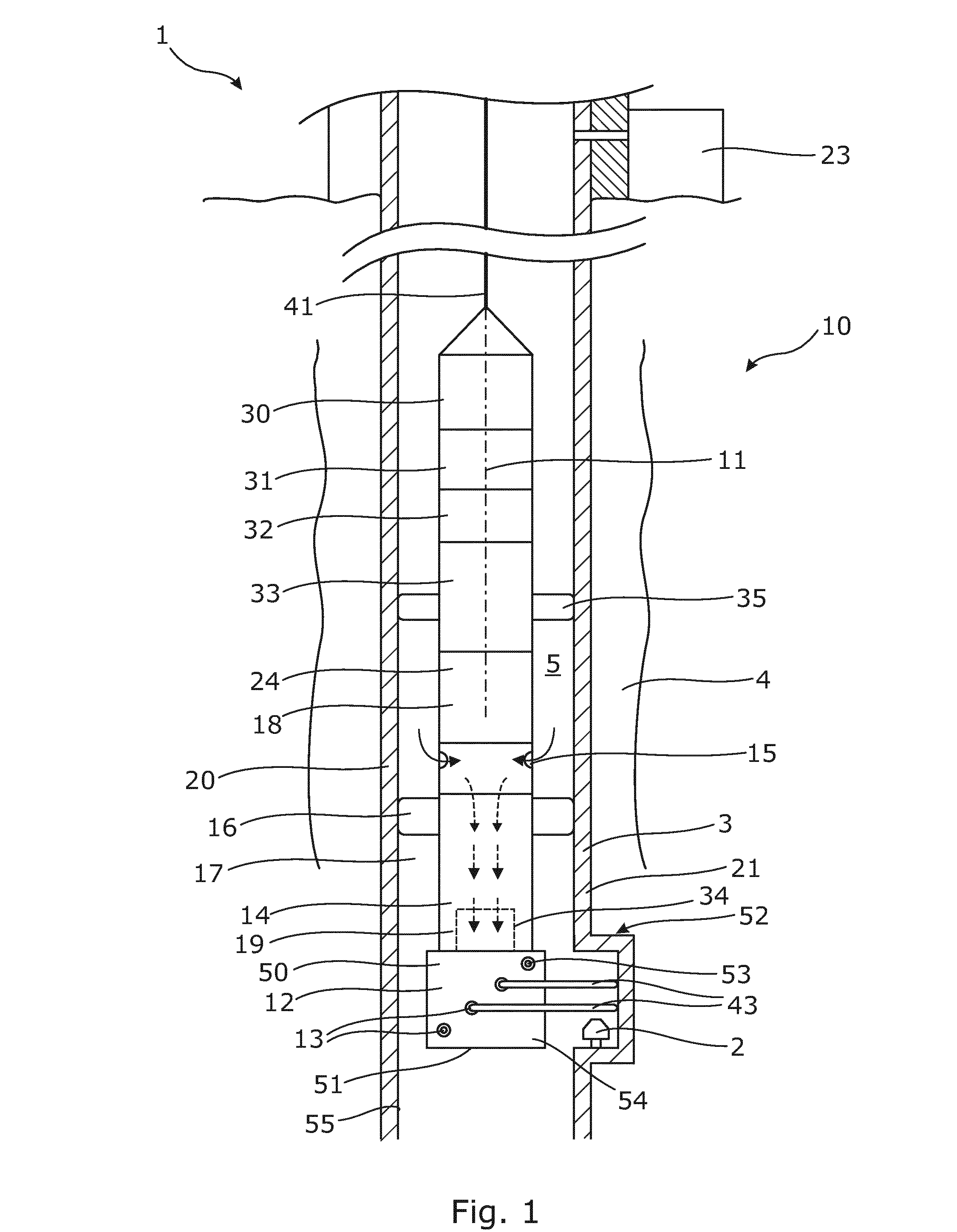
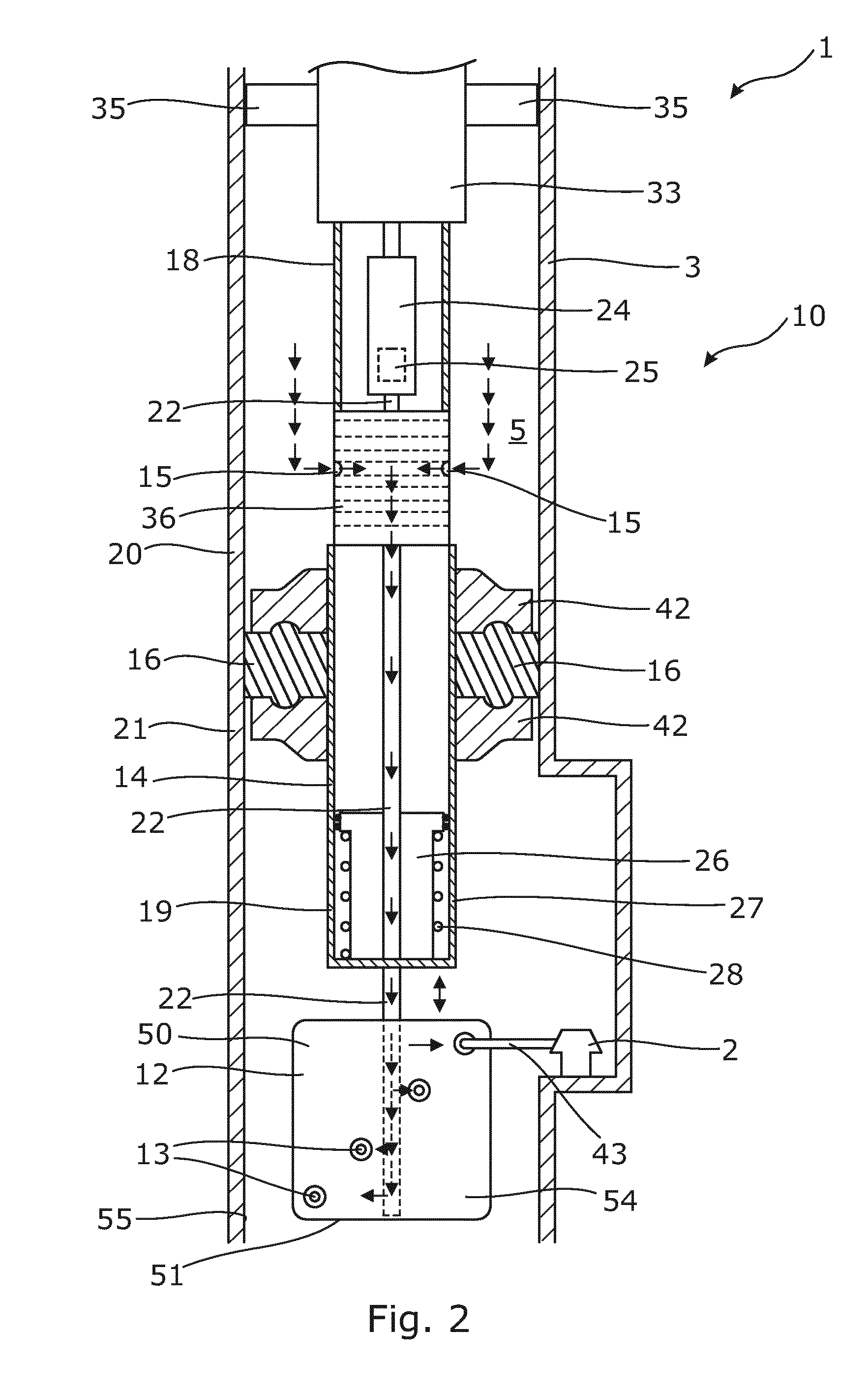
[0072]FIG. 1 shows a downhole cleaning system 1 for cleaning an element 2, such as a gas lift valve (GLV), a sleeve or a side pocket mandrel, in a casing 3 in a wellbore 4 comprising well fluid 5 having a well fluid pressure Pw. The downhole cleaning system 1 comprises the casing 3 and a wireline cleaning tool 10. The wireline cleaning tool 10 has a longitudinal direction 11, and comprises in the end furthest away from the surface a rotatable nozzle head 12 having a plurality of nozzles 13 for cleaning the gas lift valve by jetting high pressurised well fluid out through the nozzles towards the valve.

[0073]By having a cleaning tool or a wireline cleaning tool 10, the cleaning operation can be performed anywhere in the well, also in the more horizontal parts of the well. No landing nipple is required in order to perform a cleaning operation. The system is easy to use and the cleaning tool easily retrieved from the well by pulling in the wireline.

[0074]The wireline cleaning tool 10 ha...


PUM


Abstract

The present invention relates to a downhole cleaning system for cleaning an element inside a casing in a wellbore comprising well fluid having a wellbore pressure, comprising the casing, a cleaning tool having a longitudinal direction and comprising a rotatable nozzle head having a plurality of nozzles, a tool housing having an inlet being in fluid communication with the nozzles for jetting well fluid into the tool, a flow hindering element arranged on an outside of the housing dividing the tool in a first and a second tool part and dividing the casing in a first and a second casing part and a rotatable shaft connecting the nozzle head with the housing, wherein the system further comprises a pumping device for pressurising the well fluid in the first part of the casing to a pressure substantially above the wellbore pressure and above a pressure in the second part of the casing so that well fluid is pumped in through the inlet and out through the nozzles. Furthermore, the invention relates to a wireline cleaning tool and to a cleaning method.

Description

FIELD OF THE INVENTION[0001]The present invention relates to a downhole cleaning system for cleaning an element inside a casing in a wellbore comprising well fluid having a wellbore pressure, comprising the casing, a cleaning tool having a longitudinal direction and comprising a rotatable nozzle head having a plurality of nozzles, a tool housing having an inlet being in fluid communication with the nozzles for letting well fluid into the tool, a flow hindering element arranged on an outside of the housing dividing the tool in a first and a second tool part and dividing the casing in a first and a second casing part and a rotatable shaft connecting the nozzle head with the housing. Furthermore, the invention relates to a wireline cleaning tool and to a cleaning method.BACKGROUND ART[0002]During oil production, the completion needs to be optimised in order to produce as much oil as possible. Therefore, it is necessary that some valves are open and others closed. However, such valves m...

Claims


Application Information

Patent Timeline
Patent Type & Authority Applications(United States)
IPC IPC(8): E21B37/00E21B33/12E21B34/06E21B41/00
CPCE21B37/00E21B34/06E21B33/12E21B41/0078E21B23/03
Inventor HALLUNDBAEK, JORGEN
Owner WELLTEC AS
Why Eureka
Try Eureka