Pumping system

a pumping system and wellbore technology, applied in the direction of fluid removal, survey, borehole/well accessories, etc., can solve the problems of large amount of existing pumping solutions and the presence of drill pipes

Inactive Publication Date: 2013-02-21
WELLTEC AS
View PDF10 Cites 11 Cited by
  • Summary
  • Abstract
  • Description
  • Claims
  • Application Information

AI Technical Summary

Benefits of technology

[0004]It is an object of the present invention to wholly or partly overcome the above disadvantages and drawbacks of the prior art. More specifically, it is an object to provide a pumping system which is more simple and easier to submerge into a wellbore without using drill pipes or coil tubing to pump water up from the well.
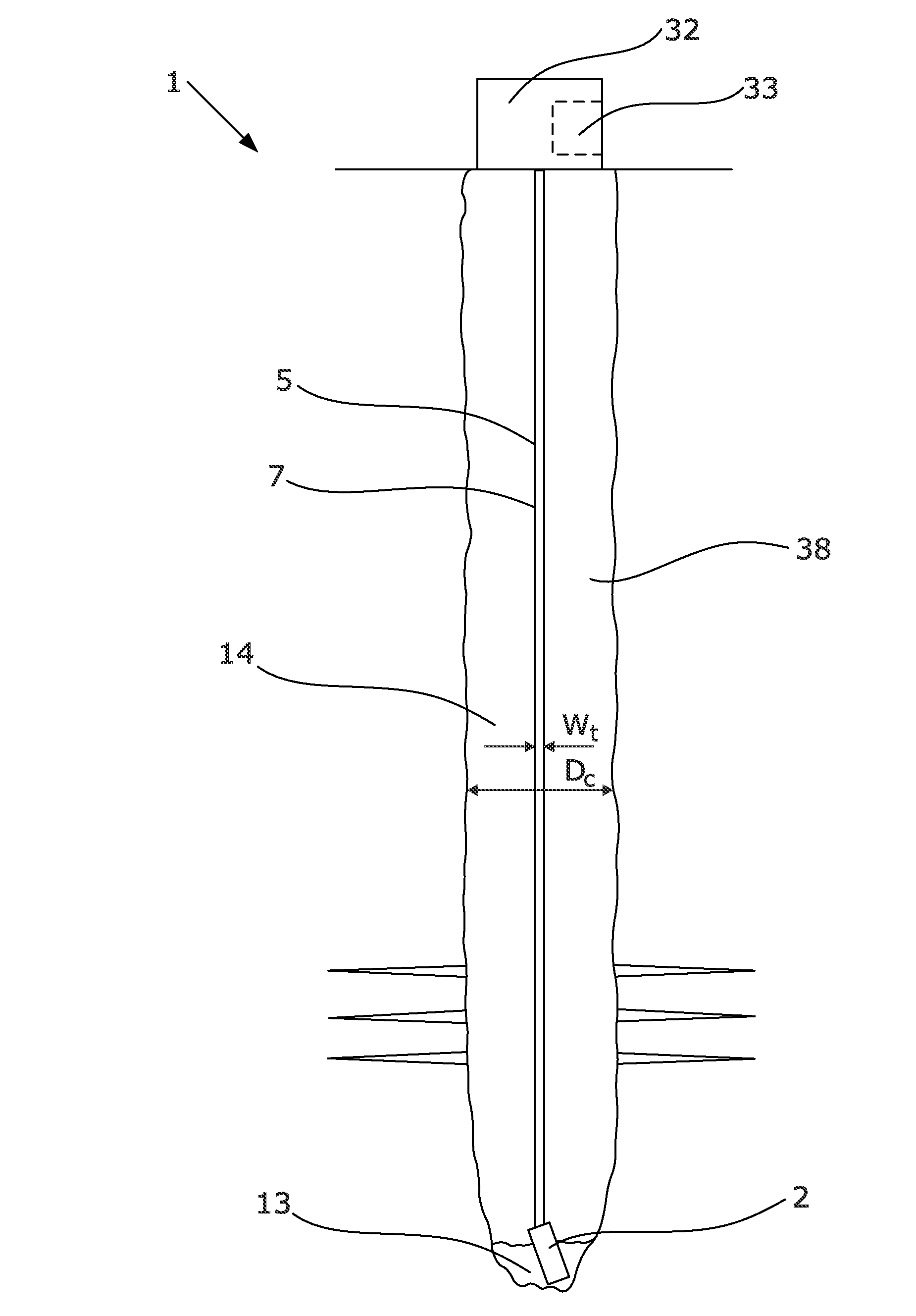
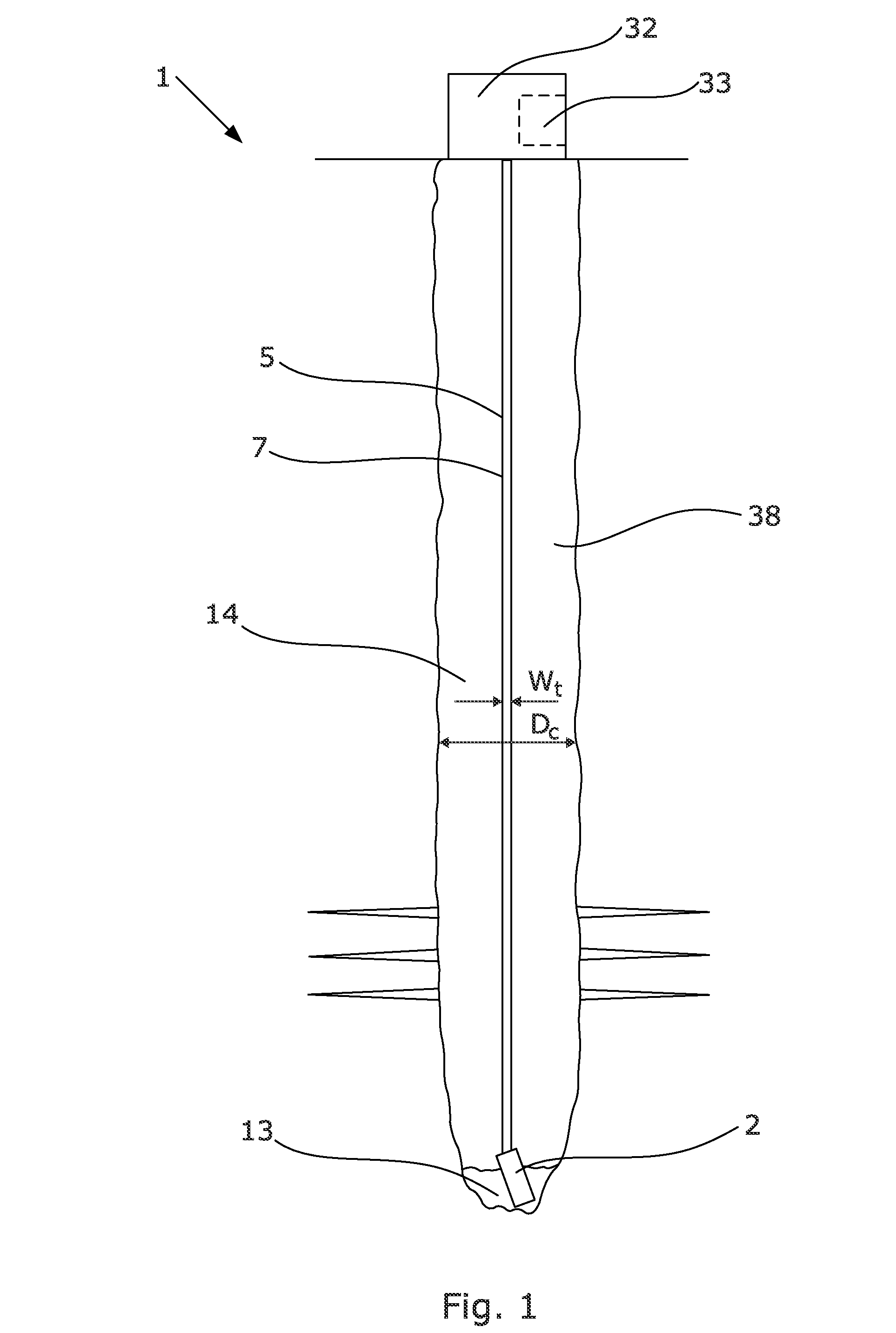
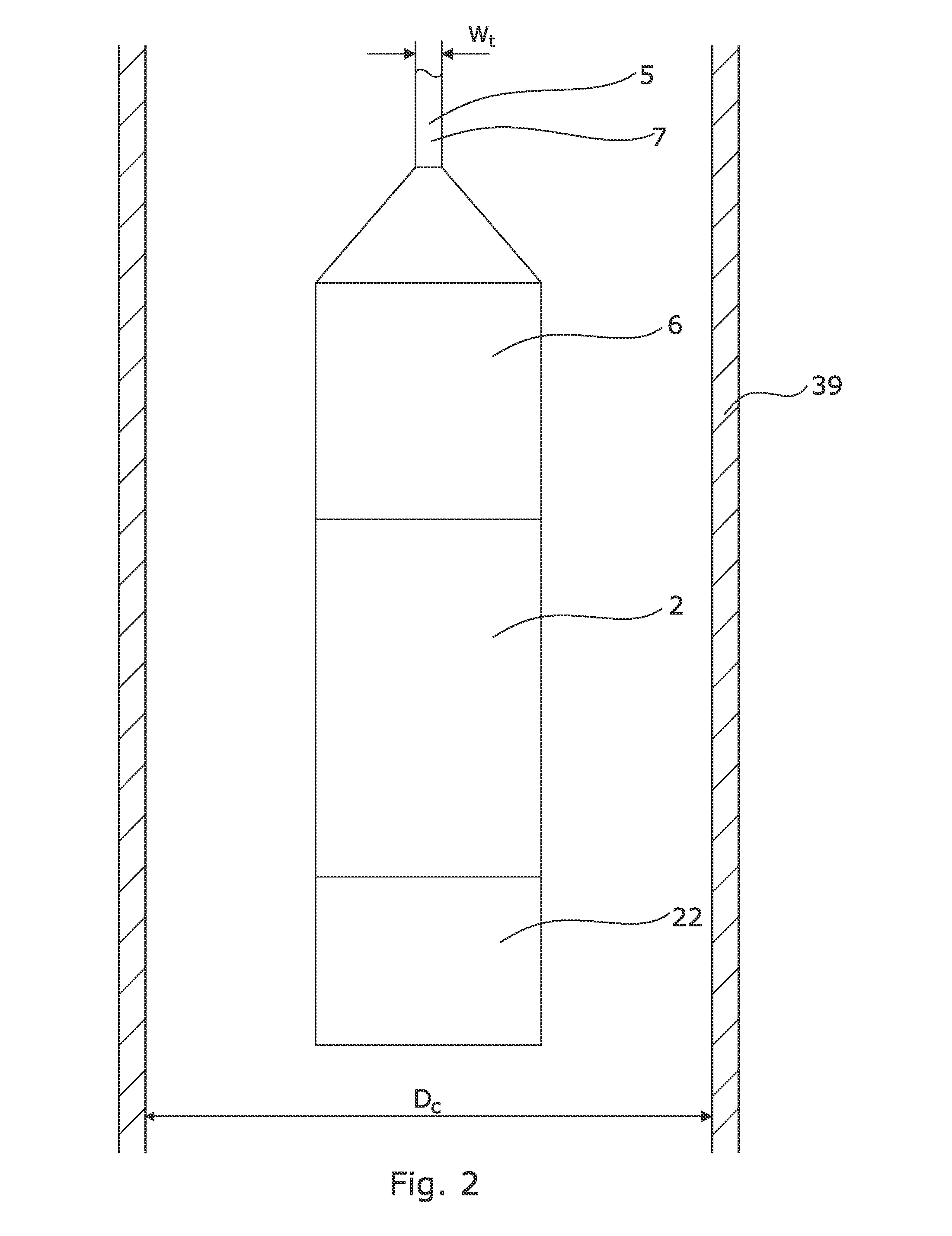
[0005]The above objects, together with numerous other objects, advantages, and features, which will become evident from the below description, are accomplished by a solution in accordance with the present invention by a wellbore pumping system submerged into a wellbore for unloading liquid from a wellbore comprising well fluid such as gas, having a wellbore pressure, comprising:
[0017]Further, a wellbore pumping system according to the invention may have a system housing having openings into which a screen or filter may be arranged preventing scales or other particles from entering the compensator device or the pump and deteriorating their function.
[0041]Moreover, the driving unit may comprise a starting means which during activation of the pump may reduce a torque delivered to the drive shaft driving the pump.

Problems solved by technology

However, the existing pumping solutions are very large and require the presence of a drill pipe or similar solutions.

Method used


Image

  • Pumping system
  • Pumping system
  • Pumping system

Examples


Embodiment Construction

[0004]It is an object of the present invention to wholly or partly overcome the above disadvantages and drawbacks of the prior art. More specifically, it is an object to provide a pumping system which is more simple and easier to submerge into a wellbore without using drill pipes or coil tubing to pump water up from the well.

[0005]The above objects, together with numerous other objects, advantages, and features, which will become evident from the below description, are accomplished by a solution in accordance with the present invention by a wellbore pumping system submerged into a wellbore for unloading liquid from a wellbore comprising well fluid such as gas, having a wellbore pressure, comprising:[0006]a pump having an inlet and an outlet,[0007]a tubing fluidly connected with the outlet of the pump, and[0008]a driving unit connected with and powered by a cable, such as a wireline, and having a rotatable drive shaft for driving the pump,

wherein the pump is a reciprocating pump comp...


PUM


Abstract

The present invention relates to a wellbore pumping system submerged into a wellbore for unloading liquid from a wellbore comprising well fluid, such as gas, having a wellbore pressure, comprising a pump having an inlet and an outlet, a tubing fluidly connected with the outlet of the pump, and a driving unit connected with and powered by a cable, such as a wireline, and having a rotatable drive shaft for driving the pump, wherein the pump is a reciprocating pump comprising at least one pumping unit having a first moving member displaceable in a housing for sucking well fluid into and out of a first chamber. Furthermore, the invention relates to a wellbore pumping method.

Description

FIELD OF THE INVENTION[0001]The present invention relates to a wellbore pumping system submerged into a wellbore for unloading liquid from a wellbore comprising well fluid, such as gas, having a wellbore pressure, comprising a pump having an inlet and an outlet, a tubing fluidly connected with the outlet of the pump, and a driving unit connected with and powered by a cable, such as a wireline, and having a rotatable drive shaft for driving the pump, wherein the pump is a reciprocating pump comprising at least one pumping unit having a first moving member displaceable in a housing for sucking well fluid into and out of a first chamber. Furthermore, the invention relates to a wellbore pumping method.BACKGROUND ART[0002]During gas production, water particles may be present in a well fluid or be produced while being transported up through the wellbore or borehole, and some of these water particles may condense on the inner face of the wellbore and subsequently flow along the inner face ...

Claims


Application Information

Patent Timeline
Patent Type & Authority Applications(United States)
IPC IPC(8): E21B43/12
CPCF04B47/06E21B43/128
Inventor HALLUNDBAEK, JORGEN
Owner WELLTEC AS
Why Eureka
Try Eureka