Recessed luminaire

a technology of luminaires and recessed lights, applied in the field of luminaires, can solve the problems of difficult alignment process, difficult to aim light sources, bulbs or lamps,

Active Publication Date: 2015-10-29
FOCAL POINT
View PDF0 Cites 66 Cited by
  • Summary
  • Abstract
  • Description
  • Claims
  • Application Information

AI Technical Summary

Benefits of technology

[0006]The following presents a simplified summary of the present disclosure in order to provide a basic understanding of some aspects of the claimed subject matter. This summary is not an extensive overview of the claimed subject matter. It is not intended to identify key or critical elements of the claimed subject matter or to delineate the scope of the claimed subject matter. The following summary merely presents some concepts of the claimed subject matter in a simplified form as a prelude to a more detailed description provided below.

Problems solved by technology

This alignment process can be difficult as the actual surface is not there when the housing is being aligned.
Current luminaires make it difficult to aim the light source (otherwise referred to as a bulb or lamp) while the luminaire is on; as such, adjusting the aim often requires turning the power off, partially disassembling the luminaire, making an adjustment in the light source aiming assembly, reassembling the luminaire and then turning the power back on to see if the adjustment correctly aimed the light source in the desired direction.
This process is made more troublesome if one or more lens and / or filters are used to shape the light emitted from the light source because often the lens and / or filters need to be carefully orientated.
As a consequence, such an aiming process may be tedious, time consuming, and expensive; however, the ability to adjust one or more of an orientation and / or an angle of a light source of a luminaire allows said luminaire to provide a variety of lighting effects in addition to down lighting, such as accent or wall-wash lighting.

Method used


Image

  • Recessed luminaire
  • Recessed luminaire
  • Recessed luminaire

Examples


Embodiment Construction

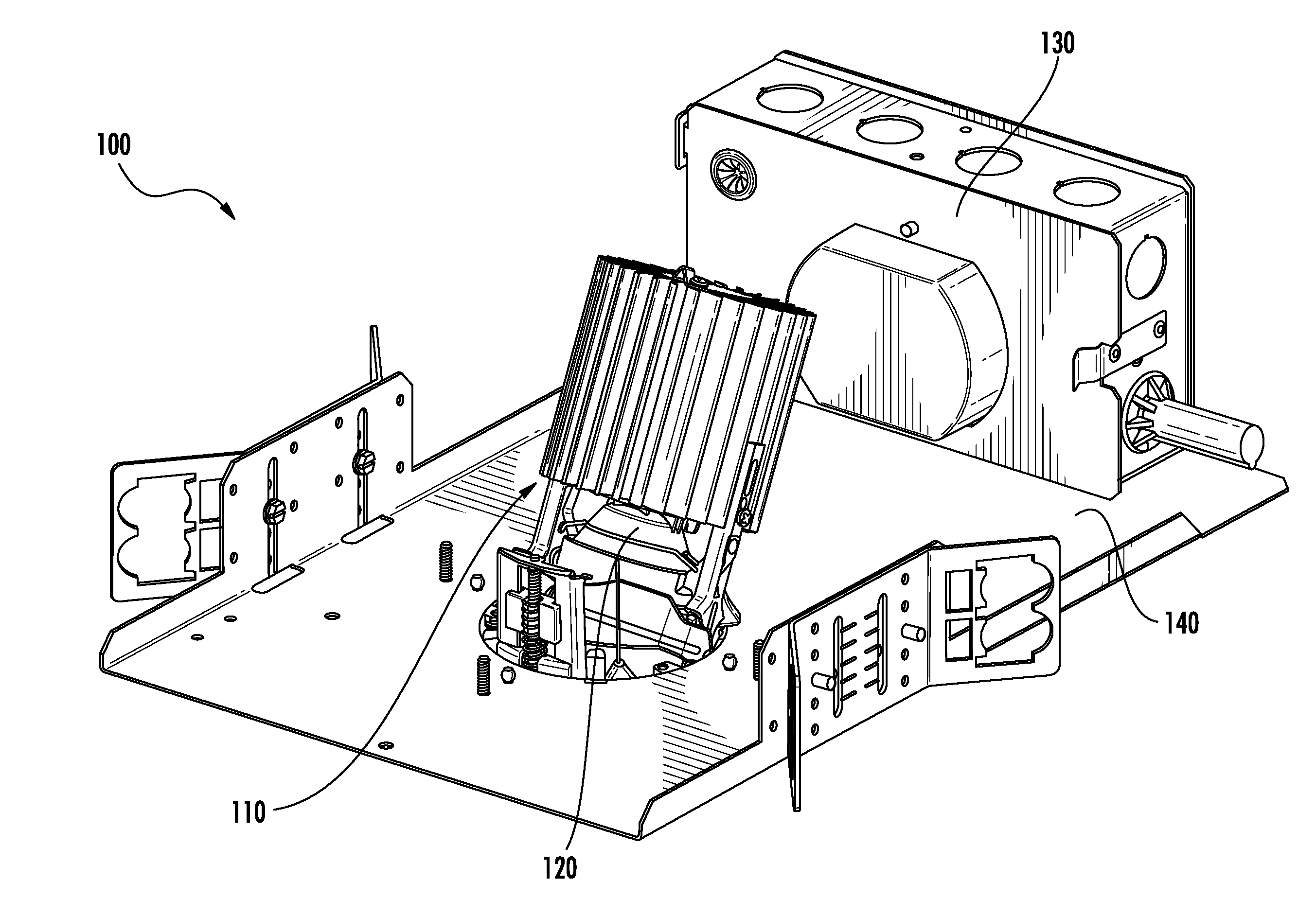
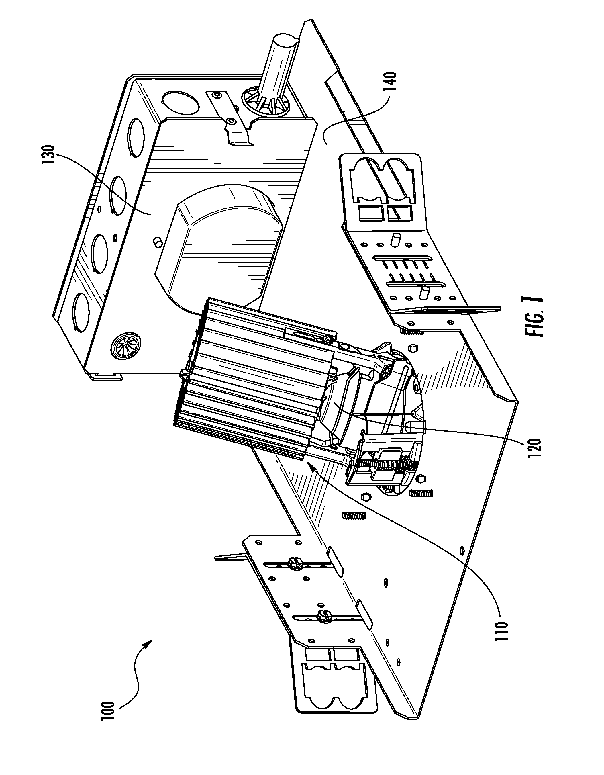
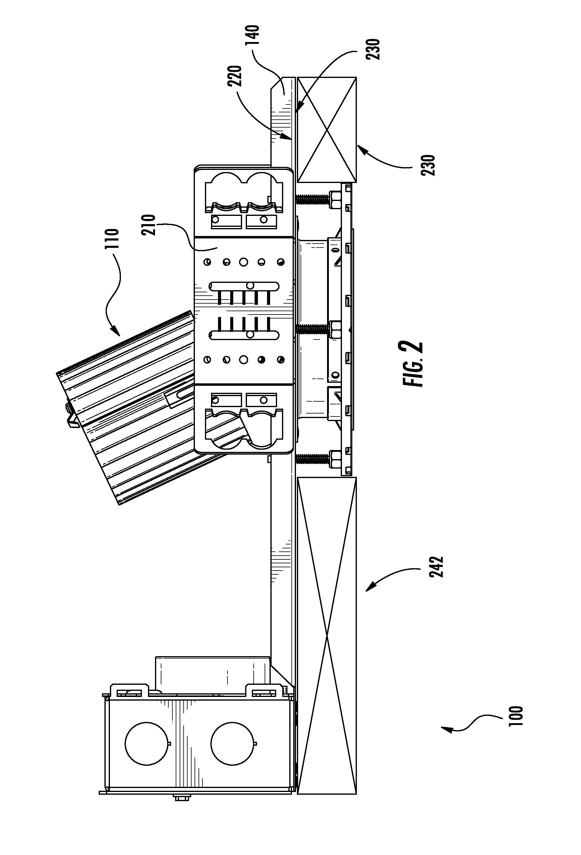
[0027]As discussed above, there is need for improved luminaire designs. Furthermore, as is apparent from the Figures described above and the description provided below, various components are disclosed below, wherein said components may be mounted to other components. Mounting may be direct or indirect and this disclosure is not intended to be limiting in this respect. It is noted that various component are described below as separate components. Two or more of these components may be combined to form a single component as appropriate, and this disclosure is not intended to be limiting in this respect.

[0028]In addition, various features are described below in greater detail. It should be noted that different combinations of these features may be combined as desired to generate luminaires with more or less features, depending on the features that are needed. Thus, it is envisioned that additional luminaires using combinations of the below described features are within the scope of th...


PUM


Abstract

A recessed luminaire is described. The luminaire may include an aiming system allowing a rotation angle and/or a tilt angle of a light source to be adjusted while the light source is in operation. Additionally, the luminaire includes a light shield that is coupled to the aiming system such that the light shield may move in relation to the tilt angle and the orientation of the light source. The aiming system may be further coupled to a support panel such that rotation of the aiming system is provided by a rotatable coupling between one or more leaf Springs of the aiming system, and an upper surface of the support panel.

Description

FIELD OF THE INVENTION[0001]The present invention relates to the field of luminaires, more particularly to the field of luminaires that may be installed in a recessed manner.BACKGROUND[0002]Light fixtures or luminaires are commonly used in a variety of commercial and residential settings. While many types of luminaires exist, one popular type is a recessed luminaire. One advantage of a recessed luminaire, depending on the design, is that the majority of the structure of the luminaire may be mounted in the ceiling or wall so that it does not noticeably extend beyond the mounting surface, thereby providing an appearance with limited visibility of constituent components when the luminaire is installed.[0003]A luminaire being installed in a ceiling is typically installed by first mounting a housing, or support panel, to a one or more ceiling supports so that the housing is aligned with the planned surface of the ceiling. This alignment process can be difficult as the actual surface is n...

Claims


Application Information

Patent Timeline
Patent Type & Authority Applications(United States)
IPC IPC(8): F21V14/02F21V14/08F21S8/02
CPCF21V14/02F21V21/04F21V14/08F21S8/02F21V21/30F21V29/74F21Y2115/10
Inventor VICE, EDWINDOUBEK, DAVID E.CHUNG, CASEY
Owner FOCAL POINT
Why Eureka
Try Eureka