
Prefabricated walking boot

a walking boot and prefabricated technology, applied in the field of orthotic braces and supports, can solve the problems of irritating causing knee, hip, back pain, etc., and achieve the effect of limiting the movement of the lower body, and avoiding irritation of the medial and lateral ankle bones and calf area

Active Publication Date: 2015-11-05
SMITH JOSEPH C
View PDF5 Cites 0 Cited by
  • Summary
  • Abstract
  • Description
  • Claims
  • Application Information

AI Technical Summary

Benefits of technology

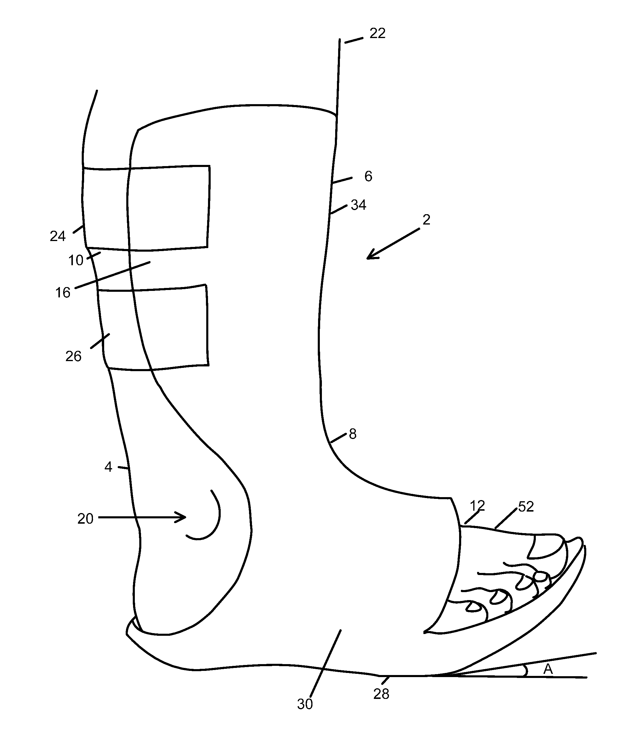
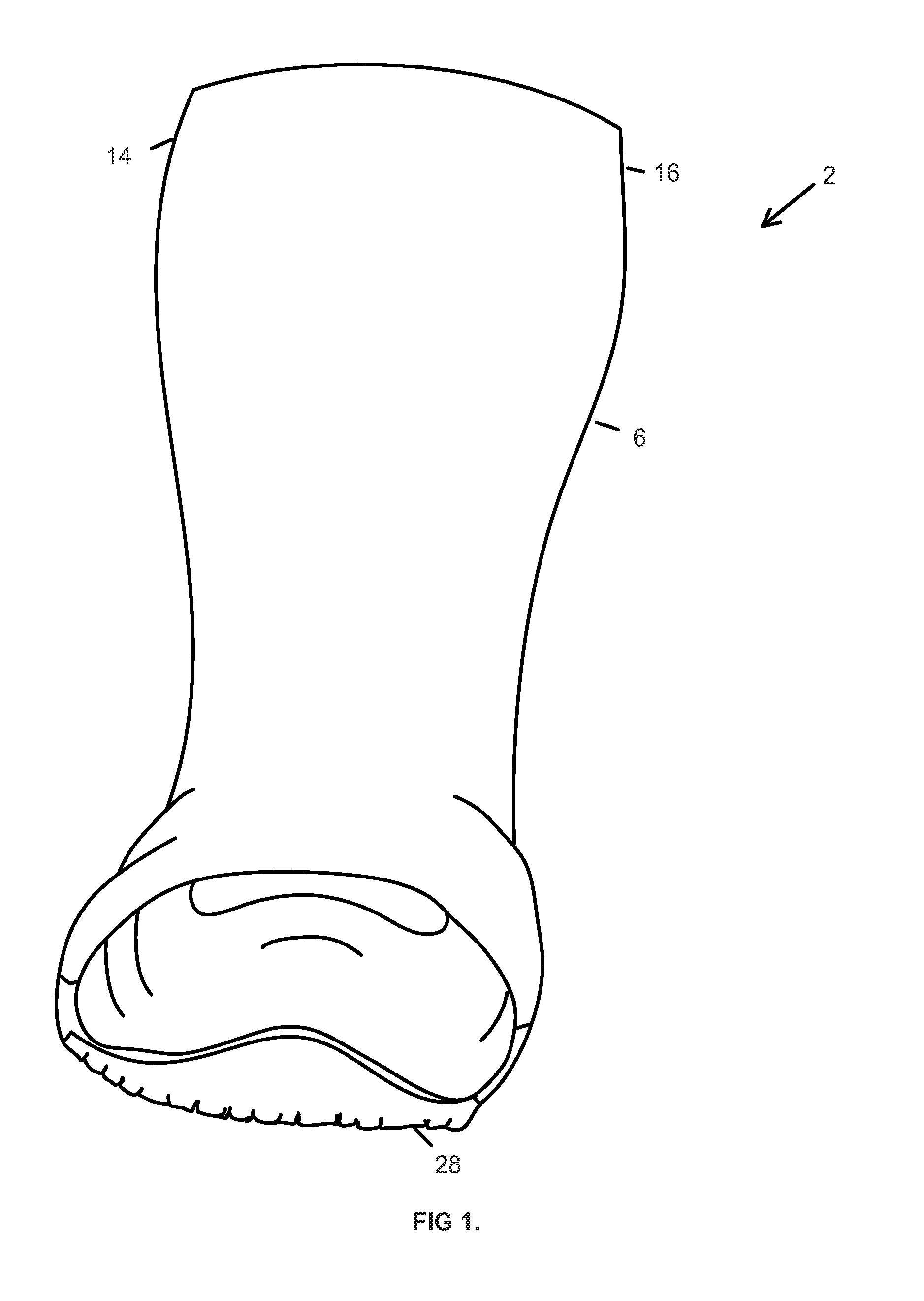
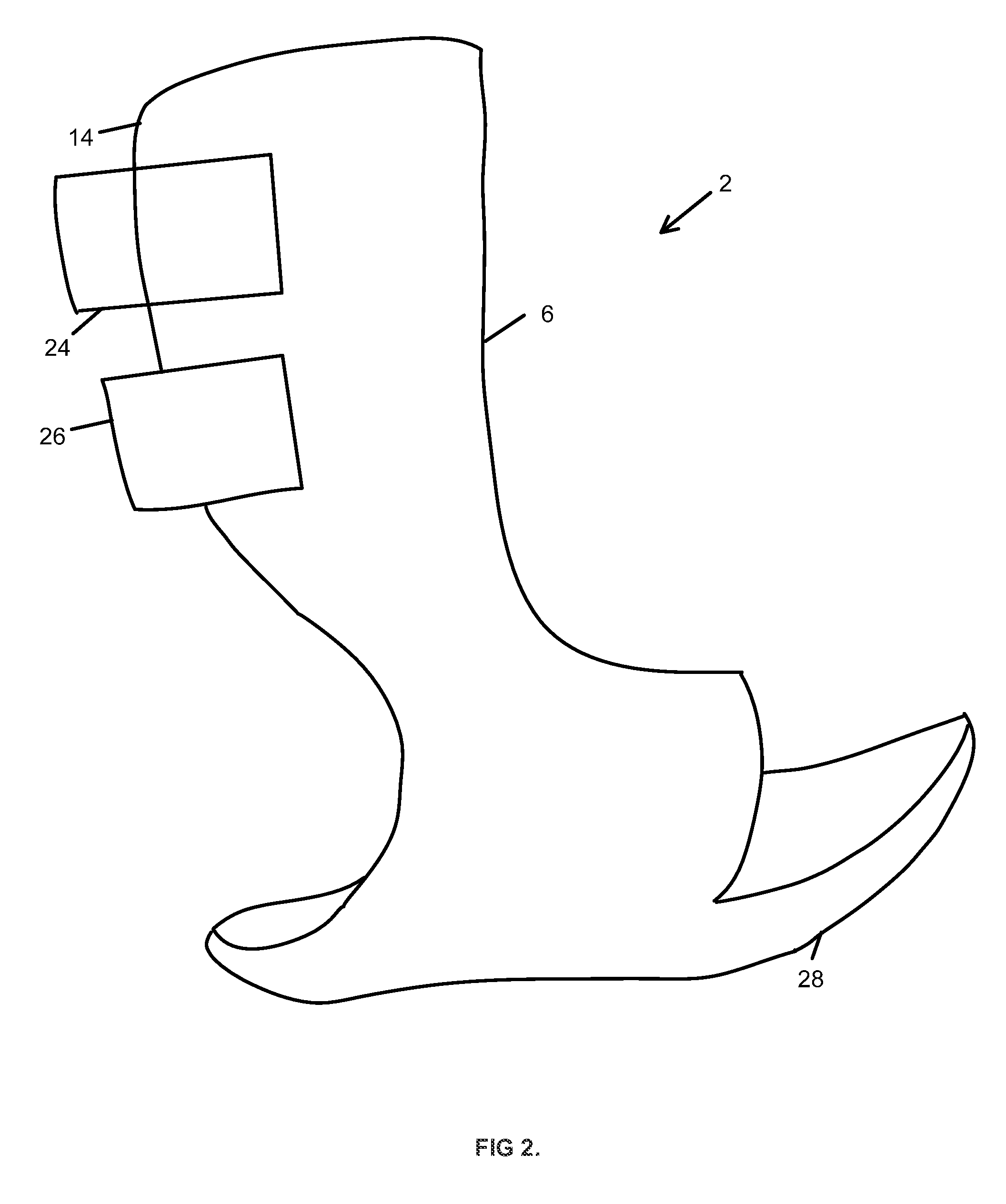
The invention is an improved walking boot device that limits the movement of the lower extremities while avoiding irritation of the ankle bones and calf area. The device has an anterior post that is angled at about 90° at the ankle joint and encompasses the front half of the calf and the back half of the forefoot. It is secured to the leg using hook and loop fastener strapping attached proximally around the calf posteriorly, away from any bony prominences. The device takes into account the difference in diameter from the ankle to the calf by curving more narrowly at the ankle and more widely at the calf for a more anatomical fit. It is low-profile and has foam inserts of varying thickness that accommodate for height inequality of opposing shoe gear.

Problems solved by technology

Many times, the walking boot posts cause irritation to the medial and lateral ankle bones and calf area where the walking boot ends proximally.
The hook and loop fastener (Velcro®) straps used in walking boots are often inadequate at limiting movement and also cause irritation over a shin.
Additionally, current walking boots frequently create knee, hip, and back pain because of a height inequality when compared to shoe gear on an opposing limb.
The above-described irritation and pain of current walking boots frequently lead patients to refuse to wear walking boots or remove walking boots prematurely, which in turn, decreases patient compliance and delays healing.

Method used


Image

  • Prefabricated walking boot
  • Prefabricated walking boot
  • Prefabricated walking boot

Examples


Embodiment Construction

[0026]The advantages of the present invention, as outlined above, are that it provides a more comfortable and accurate fit without irritation of the medial and lateral ankle bones and calf area, accommodates the varying height of opposing shoe gear, and adequately limits movement in the lower extremities while keeping the ankle joint at approximately a 90° angle.

[0027]This description of preferred embodiments is intended to be read in connection with the accompanying drawings, which are to be considered part of the entire written description. The drawing figures are not necessarily to scale and certain features of the invention may be shown exaggerated in scale or in somewhat schematic form in the interest of clarity and conciseness. In the description, relative terms such as “horizontal,”“vertical,”“up,”“down,”“top,”“bottom,”“distal,”“proximal,”“dorsal,”“plantar,”“lateral,”“medial,”“anterior,” and “posterior” as well as derivatives thereof (e.g., “horizontally,”“downwardly,”“upward...


PUM


Abstract

The present invention includes a walking boot device which immobilizes the ankle at about a 90° angle using a single anterior post that is angled at about 90° at an ankle joint from a lateral view, and encompasses an anterior one half of a calf proximally, and a dorsal one half of a forefoot distally. The post includes medial and lateral wings. The present invention defines an area for a medial and lateral malleolus and is narrow at the ankle and wider at the calf for a more anatomical fit. The present invention is secured to a leg using hook and loop fastener (Velcro®) strapping attached proximally around the calf posteriorly, away from any bony prominences. The hook and loop fastener (Velcro®) strapping is attached to the medial and lateral wings through brackets that are riveted into the wings. The present invention further includes foam inserts and a pneumatic bladder.

Description

CROSS REFERENCE TO RELATED APPLICATION[0001]This application is a continuation of U.S. application Ser. No. 14 / 013,800, filed Aug. 29, 2013.FIELD OF THE INVENTION[0002]The present invention relates generally to orthopedic and orthotic braces and supports, and more specifically to a prefabricated walking boot which serves as an ankle and foot brace or support.BACKGROUND OF THE INVENTION[0003]Orthopedic and orthotic braces and supports are used to immobilize lower extremities to allow for healing and avoiding further damage of the lower extremities Ankle-foot orthosis (AFO), in particular, is used to treat numerous ailments that may affect an ankle and / or foot. One type of AFO is a cast walker or walking boot. A cast walker allows a patient to put weight on an injured area, unlike a non-walking cast which requires that the patient keep weight entirely off the injured area by relying on crutches to walk.[0004]In current practice, walking boots are made with two straight posts that come...

Claims


Application Information

Patent Timeline
Patent Type & Authority Applications(United States)
IPC IPC(8): A61F5/01
CPCA61F5/0111
Inventor SMITH, JOSEPH C.
Owner SMITH JOSEPH C
Learn More