Micro-electrical-mechanical system (MEMS) microphone

a technology of mechanical systems and microphones, applied in the field of micro-electricalmechanical systems (mems) microphones, to achieve the effect of reducing the probability of micro-particles

Active Publication Date: 2015-11-05
SOLID STATE SYST
View PDF1 Cites 5 Cited by
  • Summary
  • Abstract
  • Description
  • Claims
  • Application Information

AI Technical Summary

Benefits of technology

[0013]The invention provides MEMS microphone, and can reduce the probability for the micro-particles

Problems solved by technology

This phenomenon would reduce the vibration of the diaphragm 108 during sensing the acoustic source,

Method used


Image

  • Micro-electrical-mechanical system (MEMS) microphone
  • Micro-electrical-mechanical system (MEMS) microphone
  • Micro-electrical-mechanical system (MEMS) microphone

Examples


Embodiment Construction

[0026]Reference will now be made in detail to the present preferred embodiments of the invention, examples of which are illustrated in the accompanying drawings. Wherever possible, the same reference numbers are used in the drawings and the description to refer to the same or like parts.

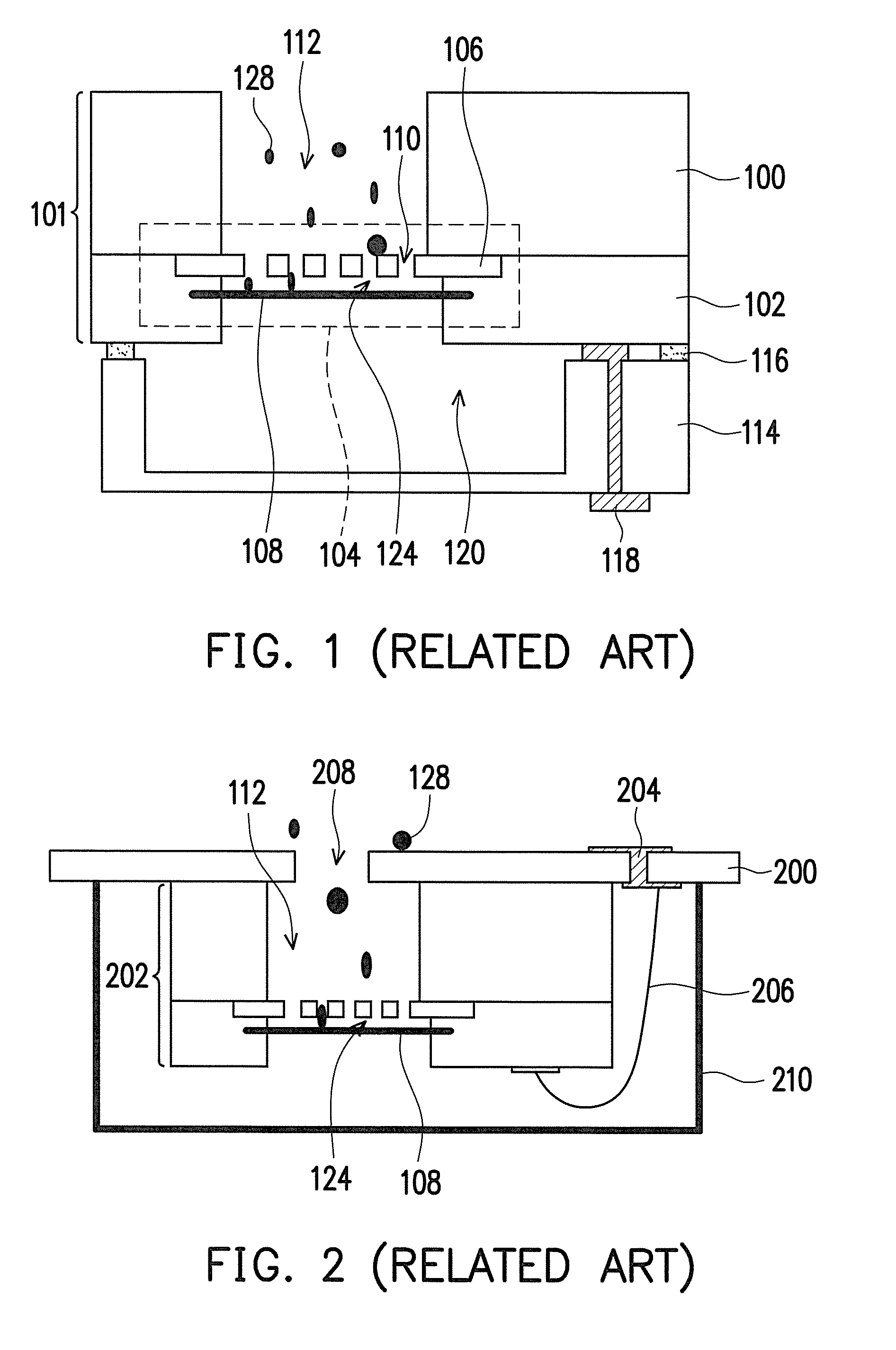
[0027]The invention investigates into the conventional MEMS microphone, in which the micro-particles very possibly enter the cavity from the acoustic hole, and then enter the chamber when passing the venting holes. As a result, the performance for the diaphragm may be reduced or even that the diaphragm does not work. The invention then provides multiple embodiments for description but not just limited to the embodiments as provided. Further a proper combination may be made between embodiments.

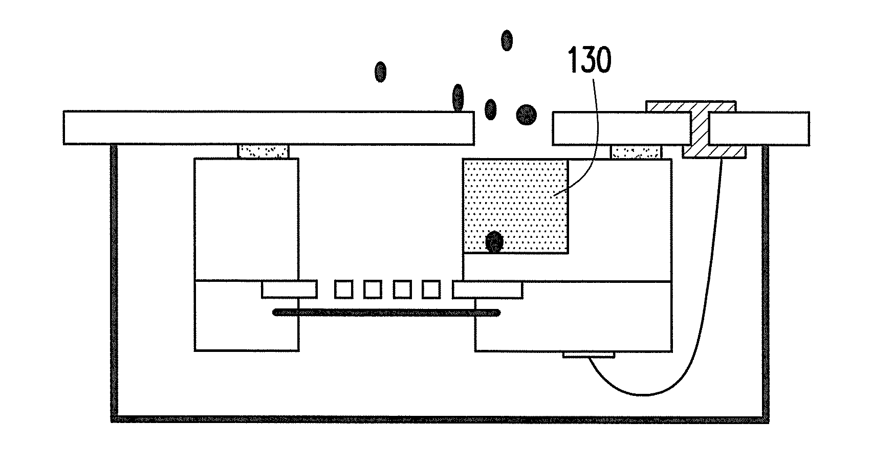
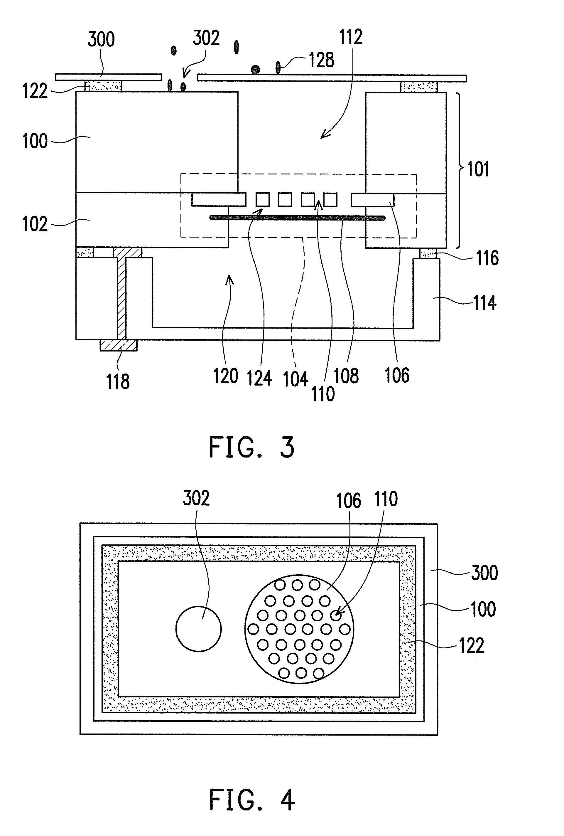
[0028]FIG. 3 schematically illustrates a cross-sectional view of a MEMS microphone, according to an embodiment of the invention. FIG. 4 schematically illustrates a top view of a part of the MEMS microphone in FI...


PUM


Abstract

A micro-electrical-mechanical system (MEMS) microphone includes a MEMS structure, having a substrate, a diaphragm, and a backplate, wherein the substrate has a cavity and the backplate is between the cavity and the diaphragm. The backplate has multiple venting holes, which are connected to the cavity and allows the cavity to extend to the diaphragm. Further, an adhesive layer is disposed on the substrate, surrounding the cavity. A cover plate is adhered on the adhesive layer, wherein the cover plate has an acoustic hole, dislocated from the cavity without direct connection.

Description

CROSS-REFERENCE TO RELATED APPLICATION[0001]This application claims the priority benefit of Taiwan application serial no. 103115580, filed on Apr. 30, 2014. The entirety of the above-mentioned patent application is hereby incorporated by reference herein and made a part of this specification.BACKGROUND OF THE INVENTION[0002]1. Field of the Invention[0003]The present invention generally relates to Micro-Electrical-Mechanical System (MEMS) microphone, in particular, to a MEMS microphone with effects of dust resistance.[0004]2. Description of Related Art[0005]The MEMS microphone is a microphone device with rather tiny size and is fabricated by semiconductor fabricating processes, so that it can be connected to integrated circuit in semiconductor fabricating processes.[0006]FIG. 1 schematically illustrates a conventional MEMS microphone. In FIG. 1, the conventional MEMS microphone includes a MEMS structure 101. The MEMS structure 101 includes a substrate 100. The substrate 100 can be se...

Claims


Application Information

Patent Timeline
IPC IPC(8): B81B7/00H04R23/00
CPCB81B7/0058H04R23/006B81B7/0006B81B2201/0257H04R2201/003H04R19/005H04R2460/11
Inventor HSIEH, TSUNG-MINLEE, CHIEN-HSINGTSAI, CHENG-WEILIOU, JHYY-CHENG
Owner SOLID STATE SYST
Why Eureka
Try Eureka