Tubular vibration-damping device

Active Publication Date: 2015-11-12
TOKAI RUBBER IND LTD
View PDF7 Cites 5 Cited by
  • Summary
  • Abstract
  • Description
  • Claims
  • Application Information

AI Technical Summary

Benefits of technology

[0058]In particular, with this embodiment, the outer circumference surface of the stopper support part 24 is an inclined surface, and as the upper stopper rubber 30 is elastically deformed and gets into the recess 20, based on the guiding action and component force action of this, the upper stopper rubber 30 more efficiently undergoes swelling deformation to the outer circumference side. In fact, with the upper stopper rubber 30 that is elastically deformed so as to get into the recess 20, there is greater deformation rigidity to the radial direction inward by the stopper support part 24, so resistance force in relation to the abutting reaction force to the locking part 22 can also be sufficiently ensured.
[0059]In addition, the outer diameter dimension of the base end part of the upper stopper rubber 30 is larger than the outer diameter dimension of the tip end surface of the stopper support part 24, so during compression deformation in the axial direction of the upper stopper rubber 30, elastic deformation in the direction of getting into the recess 20 at the outer circumference part of the upper stopper rubber 30, and thus swelling deformation of the upper stopper rubber 30 in the part opposite to the locking part 22 in the radial direction, can be more efficiently generated.
[0060]Furthermore, with this embodiment, in the standalone state before mounting of the suspension member mount 10, the top end surface of the stopper support part 24 that supports the upper stopper rubber 30 is set to be positioned further inward in the axial direction than the tip end part of the locking part 22. By so doing, the tip end part of the locking part 22 is positioned facing opposite in the radial direction to the upper stopper rubber 30 above the stopper support part 24, so when the upper stopper rubber 30 undergoes swelling deformation to the outer circumference side along with input of a load in the axial direction as described above, the swelling deformation part can be more efficiently abutted against the locking part 22.
[0061]Therefore, with the suspension member mount 10 of this embo

Problems solved by technology

However, with the outer tube member made of synthetic resin, because of permanent set-in fatigue due to heat or changes over time, it was difficult to obtain stable press fitting fixing force on the mounting hole over a long time, and it was difficult to ensure sufficient pull-out resistance force in the axial direction.
However, when an attempt is made to enlarge the projection height of the locking projection to increase the pull-out resistance force, there are cases where the locking projection becomes an obsta

Method used


Image

  • Tubular vibration-damping device
  • Tubular vibration-damping device
  • Tubular vibration-damping device

Examples


Example

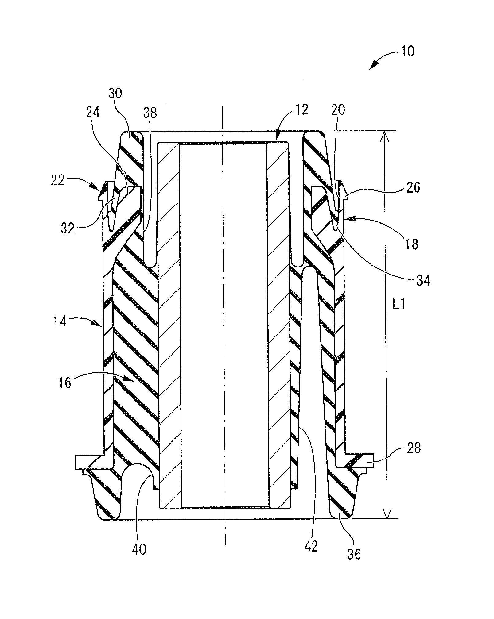
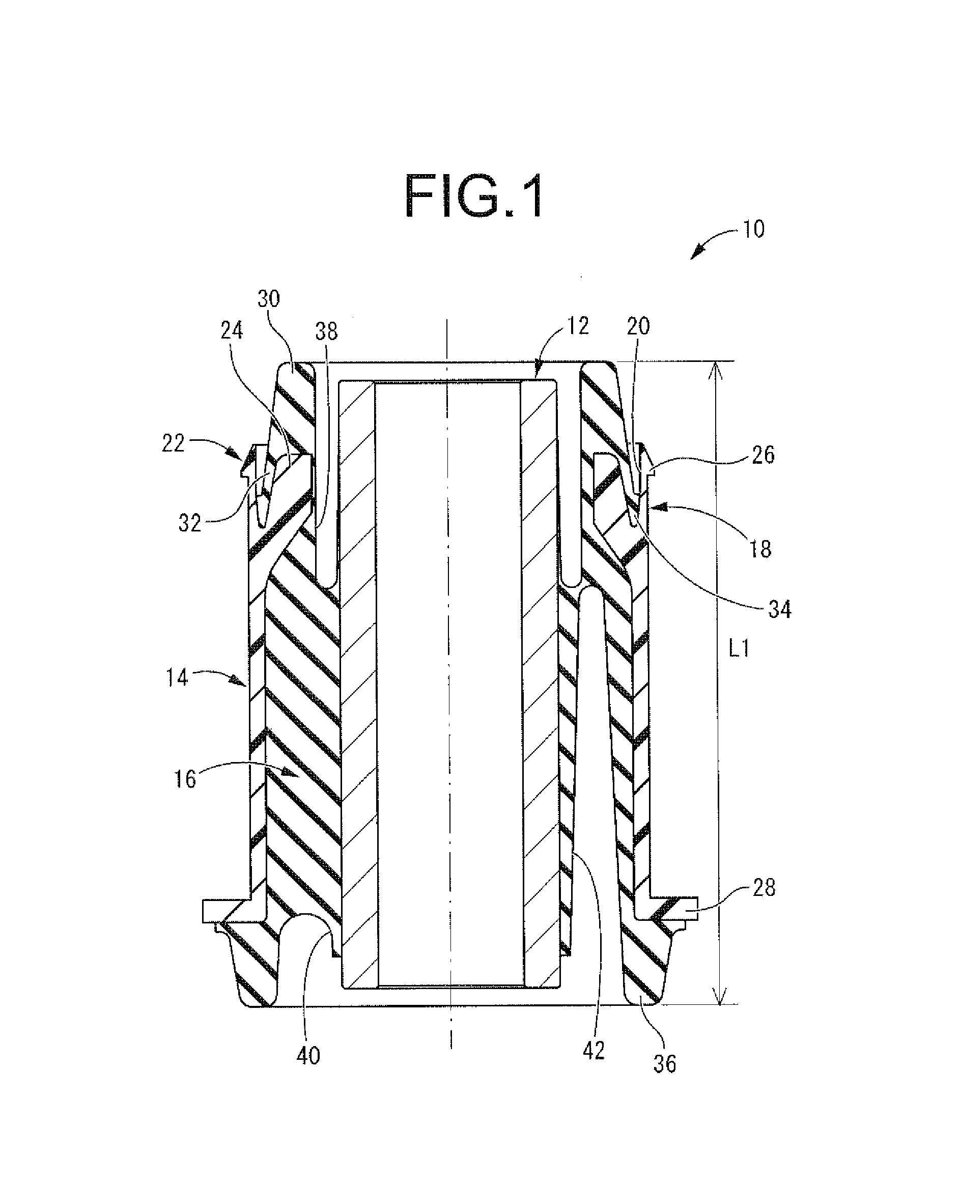
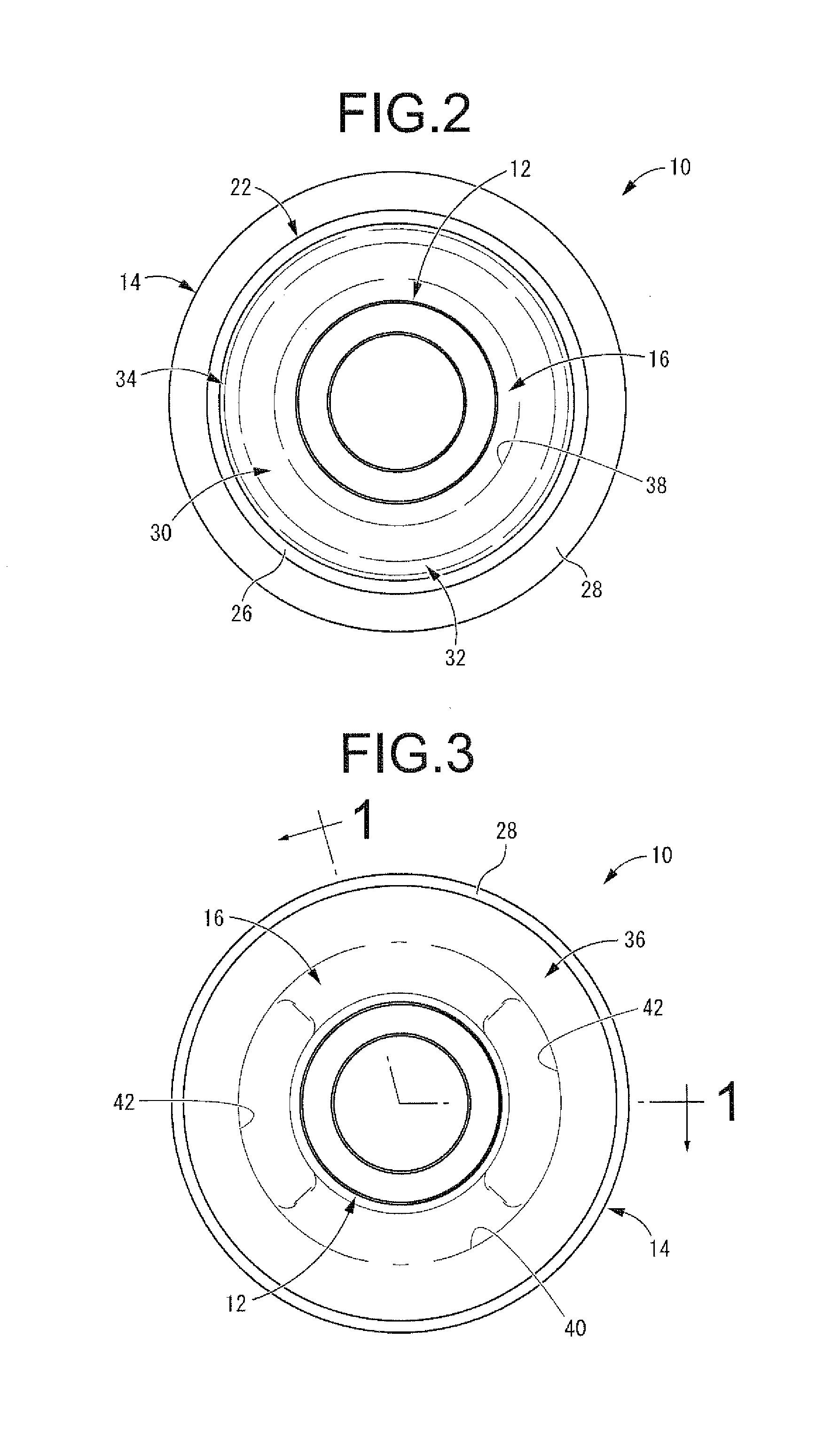
[0034]In FIGS. 1 to 3, as a first embodiment of the tubular vibration-damping device constituted according to the present invention, a suspension member mount 10 is shown. The suspension member mount 10 has a constitution for which an inner shaft member 12 is inserted into an outer tube member 14 while being separated by a designated distance, wherein the inner shaft member 12 and the outer tube member 14 are elastically coupled by a main rubber elastic body 16. With the description hereafter, as a rule, the vertical direction means the vertical direction in FIG. 1.

[0035]In more specific detail, the inner shaft member 12 is formed using a material such as metal, synthetic resin or the like, and exhibits a thick walled, small diameter roughly round cylinder shape.

[0036]The outer tube member 14 is made of a synthetic resin material that is fiber reinforced as necessary, and overall exhibits a thin walled, large diameter roughly round cylinder shape.

[0037]Also, the outer tube member 14...


PUM


Abstract

A tubular vibration-damping device including: an inner shaft member; an outer tube member; and a main rubber elastic body which couples the two members. The outer tube member is made of synthetic resin and integrally includes on its first axial end a locking part having a locking projection on its outer circumference surface and a stopper support part that supports a base end part of a stopper rubber projecting axially outward therefrom. The locking part is positioned at an outer circumference side of the stopper support part across a recess that opens axially outward of the outer tube member. Deformation of the locking part to an inner circumference side is restricted by the stopper rubber swelling to the outer circumference side along with its compressive deformation in an axial direction and abutting against an inner circumference surface of the locking part.

Description

INCORPORATED BY REFERENCE[0001]The disclosure of Japanese Patent Application No. 2013-196766 filed on Sep. 24, 2013, including the specification, drawings and abstract is incorporated herein by reference in its entirety. This is a Continuation of International Application No. PCT / JP2014 / 072956 filed on Sep. 1, 2014.BACKGROUND OF THE INVENTION[0002]1. Field of the Invention[0003]The present invention relates to a tubular vibration-damping device that is suitably used as a member mount that is mounted on an attachment part or the like of a subframe or suspension member in relation to a main body of a vehicle, a vibration damping bush mounted to an attachment part or the like at a vehicle body side of a suspension member constituting a vehicle suspension mechanism, or the like.[0004]2. Description of the Related Art[0005]From the past, as one type of vibration-damping device, a tubular vibration-damping device for which an inner shaft member and an outer tube member are coupled by a ma...

Claims


Application Information

Patent Timeline
IPC IPC(8): F16F1/38B60G11/22
CPCF16F1/38F16F1/3828B60G2204/41F16F2224/02F16F2230/0005B60G11/22B60G7/006F16F1/3842F16F1/3814
Inventor YAHATA, YUKI
Owner TOKAI RUBBER IND LTD
Why Eureka
Try Eureka