

Swivel seal assembly
- Summary
- Abstract
- Description
- Claims
- Application Information
AI Technical Summary
Benefits of technology
Problems solved by technology
Method used
Image

Examples
first embodiment
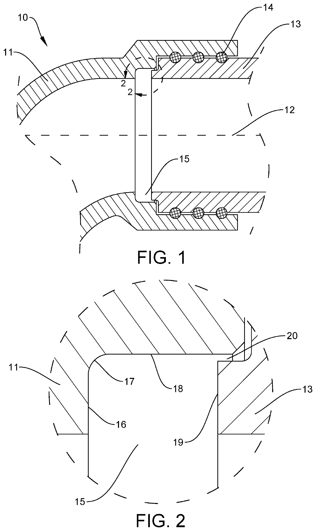
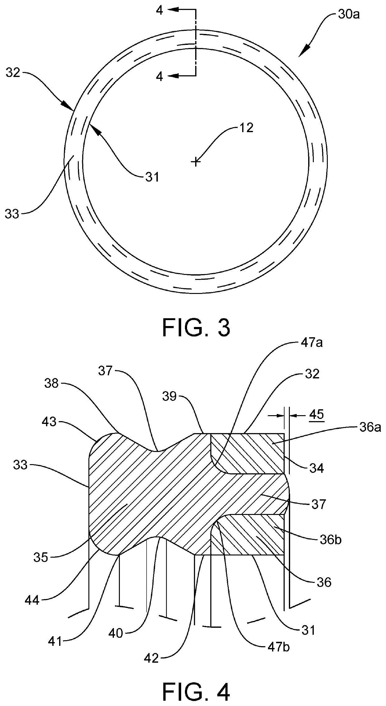
[0046]FIG. 3 is a front view of a composite seal 30a of the present invention and FIG. 4 is an enlarged sectional view of the structure of FIG. 3 taken along lines 4-4. FIG. 7 is a sectional view of the composite seal of FIG. 4 installed within the structure of FIG. 2. The composite seal 30a is configured to be disposed within the inside annular groove 15 to seal the gap 20 as will be best shown later in FIG. 7. The composite seal 30a is configured to be aligned about the longitudinal axis 12 and is delimited by an inside diameter 31 opposite an outside diameter 32 connected by a first axial side 33 opposite a second axial side 34.
[0047]This embodiment shows an elastomeric seal ring 35 bonded to at least one anti-extrusion ring 36. The at least one anti-extrusion ring 36 is disposed at the second axial side configured to be placed adjacent to the gap 20 when the composite seal is disposed within the inside annular groove 15 as is best shown in FIG. 7.
[0048]In this embodiment, the at...
second embodiment
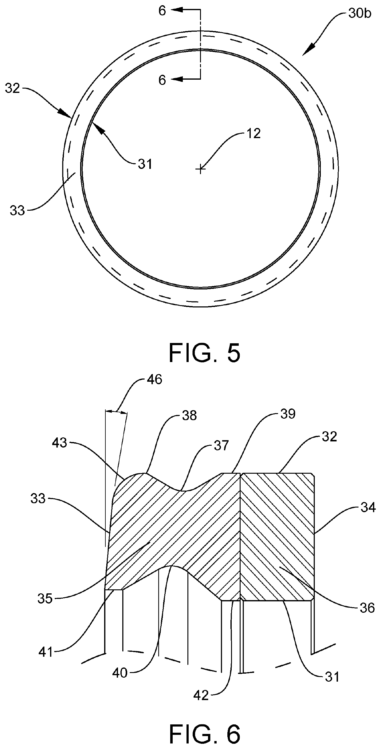
[0054]FIG. 5 is a front view of a composite seal 30b of the present invention and FIG. 6 is an enlarged sectional view of the structure of FIG. 5 taken along lines 6-6. FIG. 8 is a sectional view of the composite seal of FIG. 6 installed within the structure of FIG. 2. The structure shown in FIGS. 5 and 6 is very similar to FIGS. 3 and 4, but differs in structure as now described.
[0055]First, the at least one anti-extrusion ring 36 is a single structure. Second, the contour of the inner diameter of the elastomeric seal ring IS different. Now, the first inside sealing annular interface 41 is cylindrical. Furthermore, the first inside sealing annular interface 41 has a larger diameter in comparison to the inside diameter 31. It will be understood by those skilled in the art that the first inside sealing annular interface 41 could also have a similar diameter (not shown) in comparison to the inside diameter 31 or even a smaller diameter (not shown) in comparison to the inside diameter ...
PUM
 Abstract
Description
Claims
Application Information