
System for pairing spectacle glasses without strapping

Inactive Publication Date: 2011-01-18
LOGO
View PDF10 Cites 0 Cited by
  • Summary
  • Abstract
  • Description
  • Claims
  • Application Information

AI Technical Summary

Benefits of technology

[0010]The device according to this invention eliminates these drawbacks and holds the lenses in a rigid manner, which prevents the lenses from rotating relative to each other while making mounting and removal easier. The pad arms are no longer integral with the front face and are independent and spaced apart from each other. They are placed on either side of the nose in an ergonomic position and no longer have their origin in the very centre, which was irritating and uncomfortable and meant that the spectacles were in a position where they were pushed far forward. The pad arms have the advantage of being able to be adjusted separately without the risk of stress or damage to the lenses as could be the case in a single-piece system. Similarly, they can be replaced independently. The surface in contact with the lenses is significant which gives the assembly a greater rigidity. Finally, the lenses can be of different thicknesses without running the risk of mounting or removal problems.
[0020]Under preferable implementation conditions, the recess is precisely adapted to the width of the tab, thus preventing the lenses from swivelling.
[0032]The wearer of the spectacles according to the invention has vision close to reality which is more natural, having no field limit internally and is therefore more comfortable.
[0033]Moreover, the lenses can be independently replaced very easily, in the case of scratching or breakage or a change in vision over time.
[0035]The device according to this invention holds the lenses in a rigid manner which prevents the lenses from rotating relative to each other while making mounting and removal easier.
[0036]The pad arms are not integral with the front face, are independent and spaced apart from each other. They can be fitted on either side of the nose in an ergonomic position. Similarly, they can be independently replaced. The surface in contact with the lenses is significant, which makes the assembly more rigid. It may also be noted that the lenses can be of different thicknesses without running the risk of mounting or removal problems.

Problems solved by technology

They are placed on either side of the nose in an ergonomic position and no longer have their origin in the very centre, which was irritating and uncomfortable and meant that the spectacles were in a position where they were pushed far forward.

Method used


Image

  • System for pairing spectacle glasses without strapping
  • System for pairing spectacle glasses without strapping
  • System for pairing spectacle glasses without strapping

Examples


Embodiment Construction

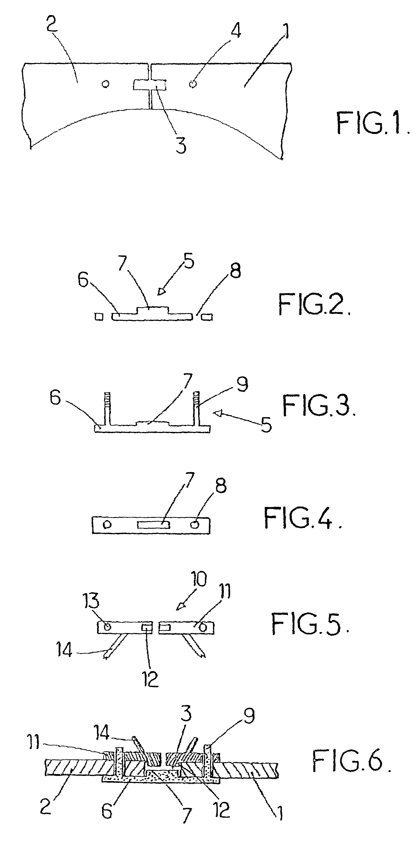
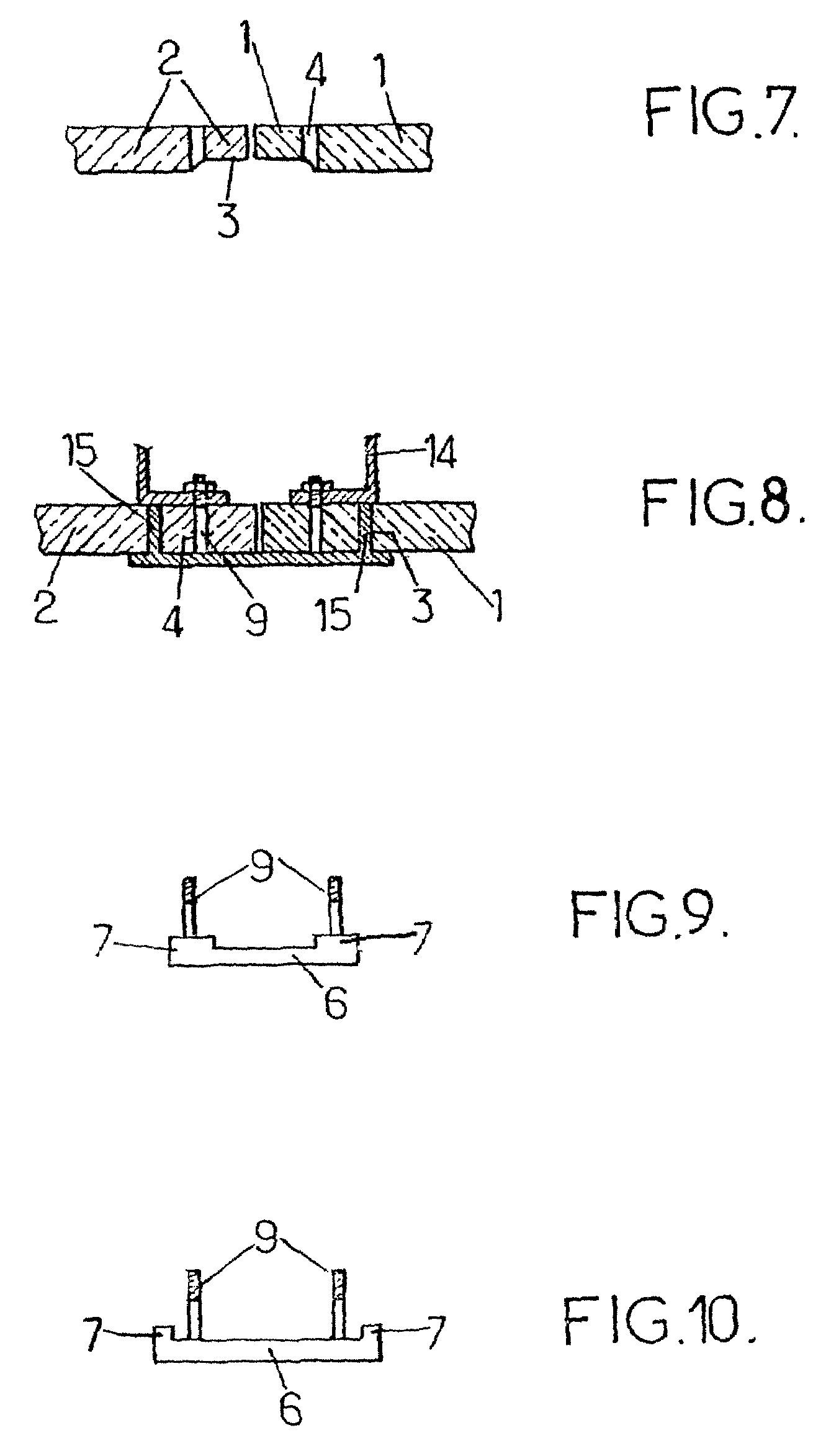
[0055]FIG. 1 shows the right lens 1 and the left lens 2, represented only in part. These lenses are placed side by side each other above the nose, they are each provided with a recess 3 at the same height as well as a perforation 4 intended for passing the screws through. The perforations 4 are also at the same height. In this embodiment they are aligned with the recesses 3 in order to minimize the width of the linking element 5 represented below.

[0056]FIG. 2 shows a linking element 5 which is constituted by a bar 6 provided with a tab 7 as well as two perforations 8, intended to allow the optical screws to pass through. The tab 7 is fitted in a median manner on the bar 6.

[0057]FIG. 3 also shows a linking element 5 comprising a bar 6, as well as a tab 7, but the perforations 8 have been replaced by screws 9, in this case fixed and produced in one piece with the bar 6.

[0058]In FIG. 4 which is a top view, perpendicular to the preceding one, it is possible to observe the tab 7 which, i...


PUM


Abstract

The invention relates to the devoid of a strap spectacles comprising two spectacle glasses (1, 2) which are arranged above the nose and each of which is preferably provided with a notch (3) embodied where said two glasses are jointed, wherein said glasses are paired by a connection element (5) which comprises a tongue (7) forming a lug for assembling the glasses (1, 2), the connection element (5) for the glasses and a kit for producing the spectacles.

Description

FIELD OF INVENTION[0001]This invention relates to a novel system for coupling rimless spectacle lenses for correcting visual deficiencies or protecting the eyes.BACKROUND[0002]Today, opticians more and more often offer spectacles of the type known as pierced-lens spectacles, the lenses of which are not rimmed by a frame but are linked by a bridge and held by screws.[0003]FR-A-1 193 800 describes spectacles the lenses of which are linked without the use of screws using metal wires and comprising a central linking part serving as a bridge for the two lenses.[0004]U.S. Pat. No. 5,771,086 for its part describes a type of spectacles comprising two independent lenses attached without a rim using a bridge constituted by a metal wire. The lenses include notching provided on the edge of the lens, on the nose side, as well as a pierced hole for passing a screw through.[0005]Their appearance ensures that these items are a great commercial success. However, they have a certain number of drawbac...

Claims


Application Information

Patent Timeline
IPC IPC(8): G02C1/02
CPCG02C1/02
Inventor LAMBERT, FRANCOIS
Owner LOGO
Learn More