Knitting machine needle

Active Publication Date: 2005-01-27
GROZ BECKERT KG
View PDF9 Cites 3 Cited by
  • Summary
  • Abstract
  • Description
  • Claims
  • Application Information

AI Technical Summary

Benefits of technology

[0009] The knitting machine needle of the invention has a needle body with a stemlike portion, extending between the butt and the hook, that is provided with a deflection, also called a meandering curve. At least one recess is embodied in the region of this deflection. This recess lends the deflection particular resilience and a pronounced stamping action. It has been demonstrated that with this provision, the requisite stability of the needle shank can be preserved, and on the other hand the tendency to hook breakage is drastically reduced, even if major impactlike loads are put on the needle. As a result, the service life of the knitting machine needles in question can be increased substantially. This is especially true for needle families or needle sets in which individual needles have only slight spacings between the butt and the hook. Especially in such needles, in which there is only a single meandering curve or in other words a single deflection between the butt and the needle, the recess proves to be especially favorable in terms of both the service life and the impact-bearing capacity.
[0011] In a preferred embodiment, the recess is embodied as a slot and extends in interrupted or uninterrupted fashion over the entire deflection. The recess can be longer than the Z-shaped deflected region; that is, it can protrude past the deflected region to one side or both sides, and in particular it can extend into or to beneath the region of the butt. The recess can also be provided in the form of a series of circular recesses or recesses of other shapes. The slot may either be embodied as a complete, unfilled punched opening, or it may be filled with a damping (energy-dissipating) material. Alternatively, the slot may be embodied not as a complete punched opening, but only as a countersunk feature or groove on one or both sides. Such embodiments lead to somewhat greater rigidity of the shank than embodiments with a complete punched opening. Filling up the punched openings or slot indentations (recesses on one or both sides and having a bottom) with damping material also the advantage that the slot does not fill up with extraneous substances such as oil and dirt, which can affect the vibration properties of the shank. The properties of the knitting machine needle then remain unchanged over its operating time, at least to the extent that these properties are determined by the properties of the shank.

Problems solved by technology

With increasing operating speed, hook breakage increases.
All needles have their limits, however, which become apparent especially at maximum operating speeds.
In needle sets which contain knitting machine needles with different butt positions, the hook breakage increases, especially in needles whose butt is especially close to the hook.

Method used


Image

  • Knitting machine needle
  • Knitting machine needle
  • Knitting machine needle

Examples


Embodiment Construction

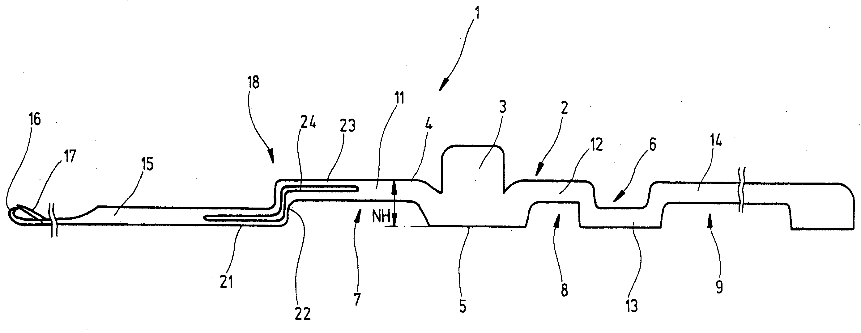
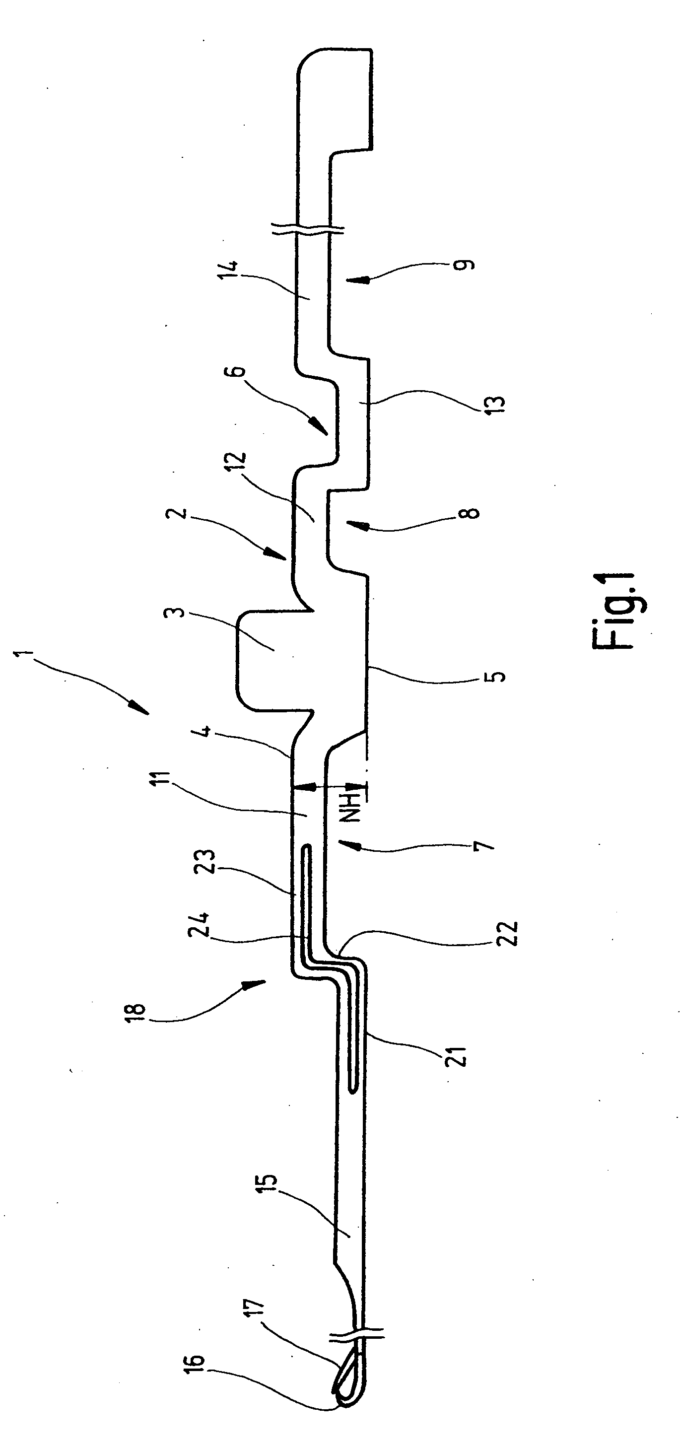
[0020] In FIG. 1, a knitting machine needle 1 is shown of the kind that can be used in particular for high-speed knitting machines. It has a flat needle body 2, which is adjoined by a butt 3 of the same thickness that protrudes at a right angle away from a narrow, striplike face 4 that defines the top side of the needle. Parallel to this face, a narrow, striplike needle back 5 is embodied on the opposite side of the needle body 2. Both the face 4 and the needle back 5 are interrupted by recesses 6, 7, 8, 9, specifically in such a way that to a certain extent the needle body 2 is formed by stems 11, 12, 13, 14 adjoining one another in meandering fashion. The height NH of the needle body extends from the face 4 to the needle back 5.

[0021] The needle body 2 is adjoined by a shank 15, which carries a hook 16 on its end. The shank 15 is elongated and straight and tapers on one end toward the hook 16. In the vicinity of the hook, a pivotably supported latch 17 may be provided. Between th...


PUM


Abstract

A knitting machine needle (1), having a butt (3) pointing away from its needle body (2) and a shank (15) extending from the needle body as far as a hook (16), has a deflection (18) which is disposed between the hook (16) and the butt (3). The deflection (18) is provided with at least one recess (24), which locally alters the wave resistance of the deflection (18) and leads to a reduction in hook breakage when the butt (3) is exposed to impacts.

Description

CROSS REFERENCE TO RELATED APPLICATIONS [0001] This application claims the priority of German Patent Application No. 103 33 172.7, filed on Jul. 22, 2003, the subject matter of which, in its entirety, is incorporated herein by reference. FIELD OF THE INVENTION [0002] The invention relates to a knitting machine needle and to a needle set which contains at least one such knitting machine needle. BACKGROUND OF THE INVENTION [0003] The service life of knitting machine needles depends, among other factors, on the operating speed of the knitting machine. The faster the machine runs, the more strongly the individual needles are accelerated and braked in the longitudinal direction. With increasing operating speed, hook breakage increases. In the past, manifold attempts have already been made to improve this situation. From U.S. Pat. No. 4,036,036, it is known, in the needle body of a knitting machine needle, to embody one or more straight, curved, angled, offset-bent, splitting, undulating ...

Claims


Application Information

Patent Timeline
IPC IPC(8): D04B35/04D04B35/02
CPCD04B35/04D04B35/02
Inventor LANDENBERGER, INGO
Owner GROZ BECKERT KG
Why Eureka
Try Eureka