

Humidity regulating apparatus
- Summary
- Abstract
- Description
- Claims
- Application Information
AI Technical Summary
Benefits of technology
Problems solved by technology
Method used
Image

Examples
first embodiment
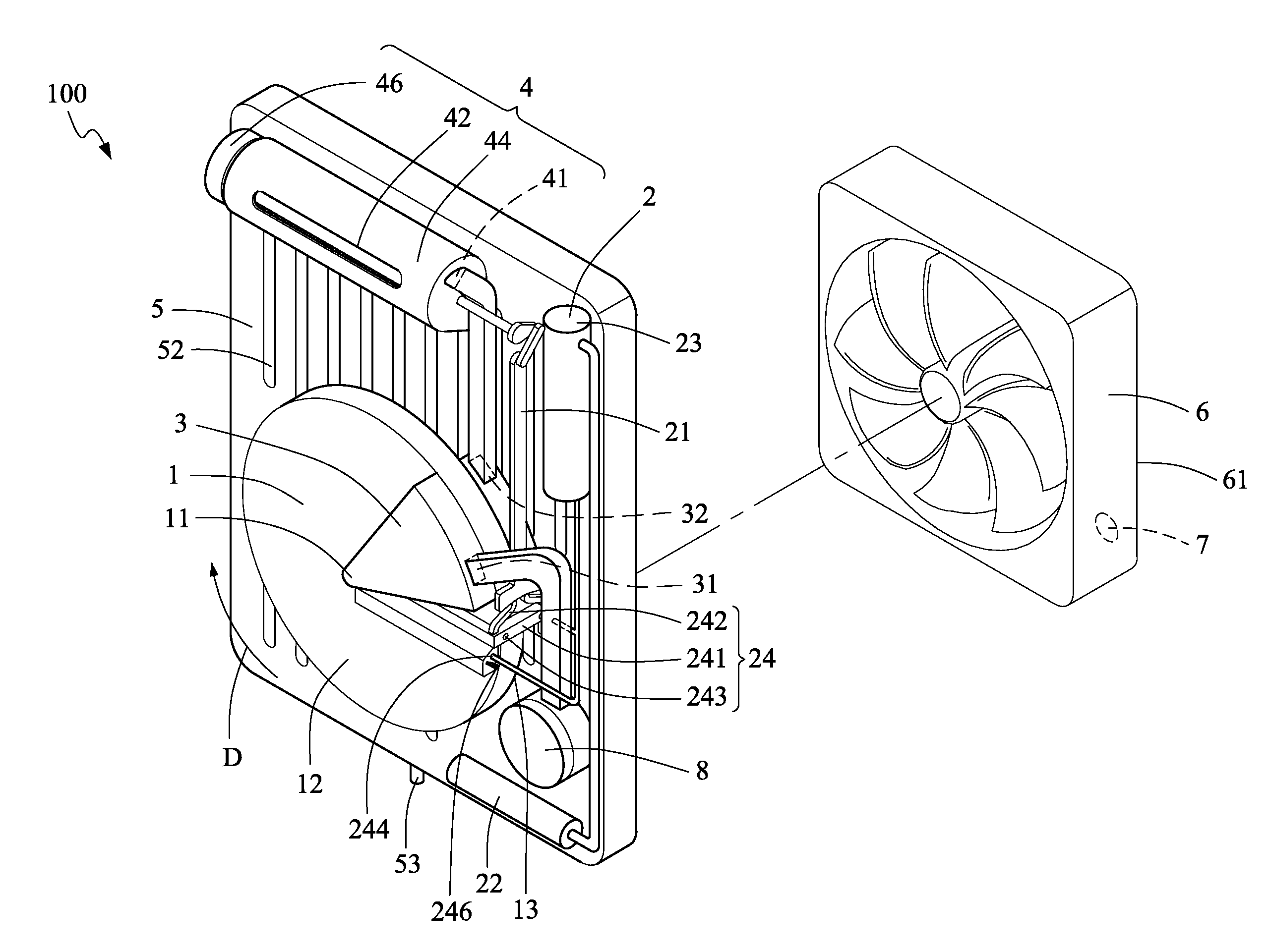
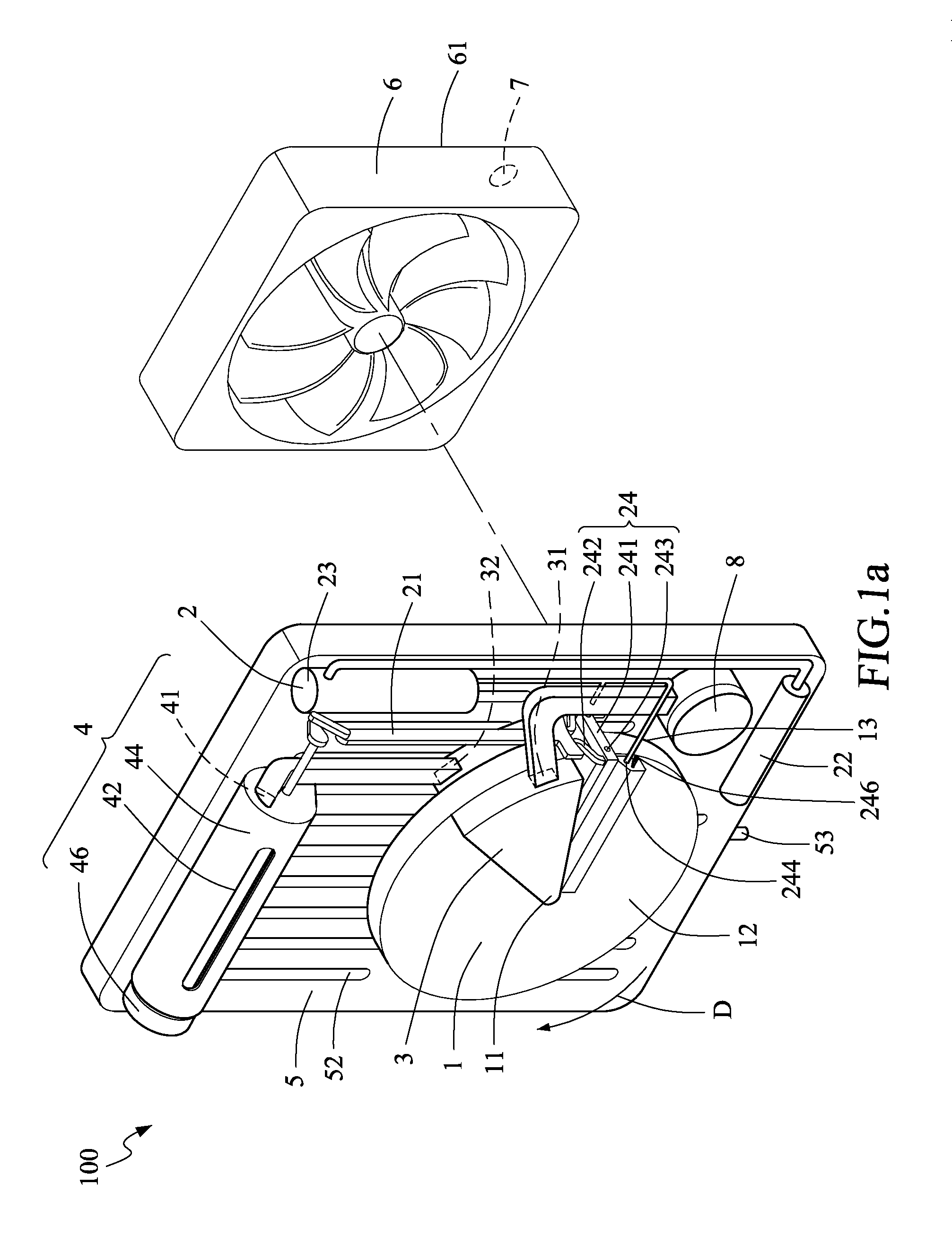
[0032]Referring to FIG. 1a, a humidity regulating apparatus 100 according to the present invention is applied in a target environment where the relative humidity is to be regulated. The humidity regulating apparatus 100 includes a hygroscopic wheel 1, a wetting means 2, a heating means 3, a transporting means 4, and a condensing means 5.
[0033]The hygroscopic wheel 1 is rotated in a direction D to absorb moisture and water surrounding the hygroscopic wheel 1. Preferably, the hygroscopic wheel 1 has a plurality of micro pores for achieving good effects of moisture absorption. For example, the hygroscopic wheel 1 is made of such hygroscopic materials as zeolite, silica gel, activated alumina and activated carbons.
[0034]The wetting means 2 is disposed in a position corresponding to the hygroscopic wheel 1 and performs a movement in relation to the hygroscopic wheel 1. The wetting means 2 is controlled to supply moisture or water to the hygroscopic wheel 1. In the first embodiment, the w...
second embodiment
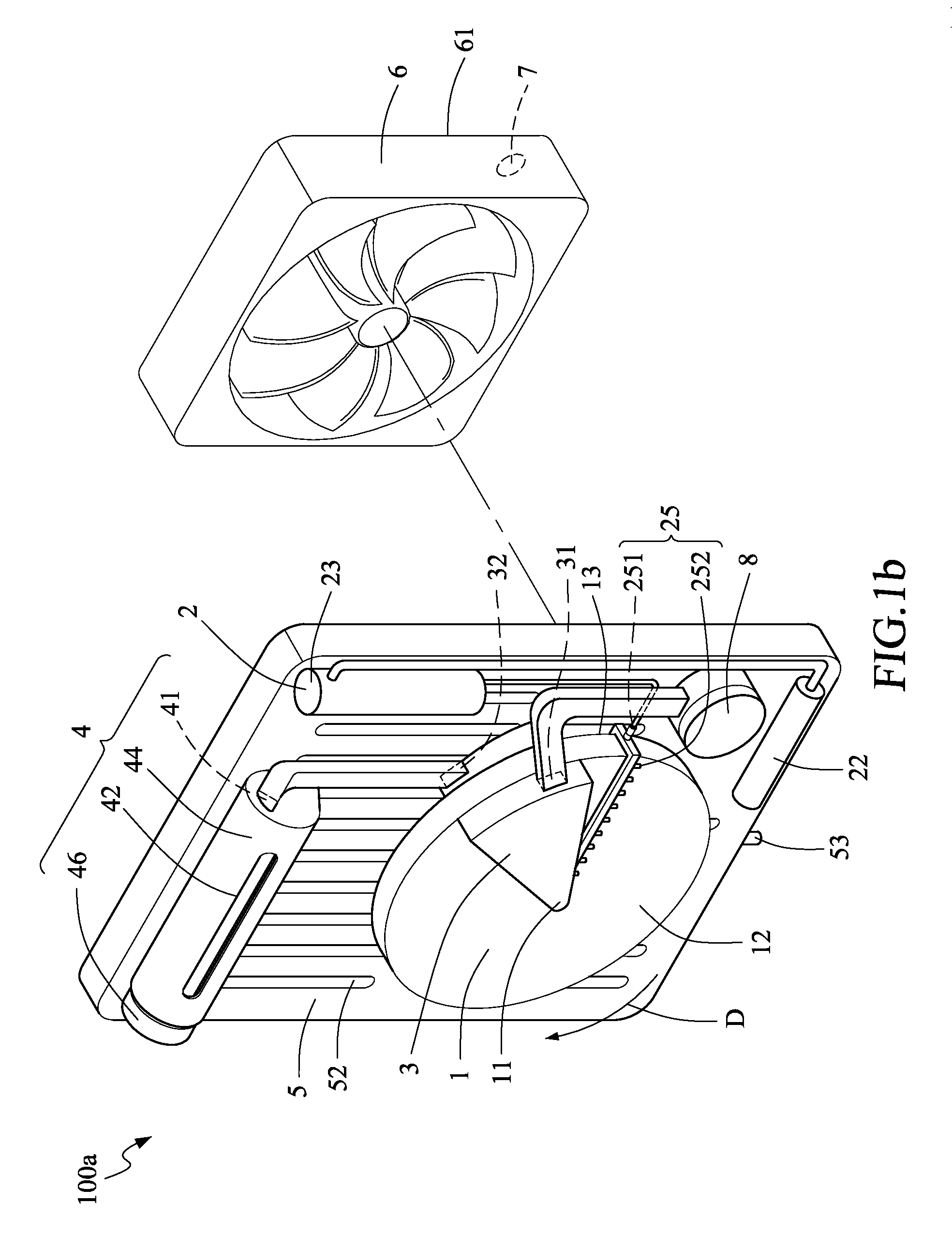
[0046]Referring to FIG. 1a and FIG. 8, when the rotary switching member 45 is switch to the dehumidifying transporting position, the linking member 21 affected by linkage of the rotary switching member 45 to move to a second position, and the two clamping members 242 of the hydraulic conducting member 24 are pressed by the linking member 21 to separate the elastic member 246 of the hydraulic conducting member 24 from the both hygroscopic surfaces 12 and 13 of the hygroscopic wheel 1 so as to avoid the attrition of the elastic member 246 caused by the rotation of the hygroscopic wheel 1. However, the present invention is not limited to this. Referring to FIG. 1b, the wetting means 2 of the humidity regulating apparatus 100a includes a water spraying member 25 according to the present invention. The water spraying member 25 includes a water inlet 251 connected to the water tank 23 and multiple water outlets 252 connected to the water inlet 251. The multiple water outlets 252 are dispo...
PUM
 Abstract
Description
Claims
Application Information