Methods and apparatus for optimizing environmental humidity

a technology of environmental humidity and optimizing methods, applied in lighting and heating apparatus, instruments, heating types, etc., can solve the problems of less than optimal or inaccurate testing, damage to chamber and dut components, and excessive moisture condensation, etc., to increase and/or decrease the humidity of the chamber

Inactive Publication Date: 2007-02-01
SIGMA SYST
View PDF35 Cites 46 Cited by
  • Summary
  • Abstract
  • Description
  • Claims
  • Application Information

AI Technical Summary

Benefits of technology

[0034]FIG. 2a is a logical flow chart showing another exemplary embodiment of the method for controlling humidity within the test chamber in accordance with the present invention, wherein water temperature is utilized to control increases and / or decreases in chamber humidity.

Problems solved by technology

This results in excessive moisture condensation on the surfaces that are at or below the dew point of the humidifying air (and even possibly submersion of certain components in more extreme cases), and can result in (i) damage to chamber and DUT components, (ii) less than optimal or inaccurate test results, and (iii) creation of hazardous conditions due to the presence of moisture along with electrical potential / current.
In reality however, such dispersion is not uniform, and the gas in the environment cannot fully support the steam as water vapor.
The water droplets when atomized into an environment with a higher temperature will result in a large percentage being supported as water vapor; however, the moisture that cannot be supported will condense as liquid water, resulting in similar problems as were encountered in the steam-type injection approach.

Method used


Image

  • Methods and apparatus for optimizing environmental humidity
  • Methods and apparatus for optimizing environmental humidity
  • Methods and apparatus for optimizing environmental humidity

Examples


Embodiment Construction

[0035] Reference is now made to the drawings wherein like numerals refer to like parts throughout.

[0036] As used herein, the term “device under test” or “DUT” refers generally to any component, material, assembly, or device which is being tested, evaluated, or conditioned. DUT's can include, without limitation, electronic or mechanical devices or assemblies, integrated circuits, semiconductors, diodes, material specimens or samples, or crystals.

[0037] As used herein, the term “humidity” refers generally to the concentration of one material in another. In the exemplary instance, humidity refers to the relative water (vapor) content within air; however, the term is also meant to encompass water content in other gases, and even the content of non-water liquids carried within air or other types of gases.

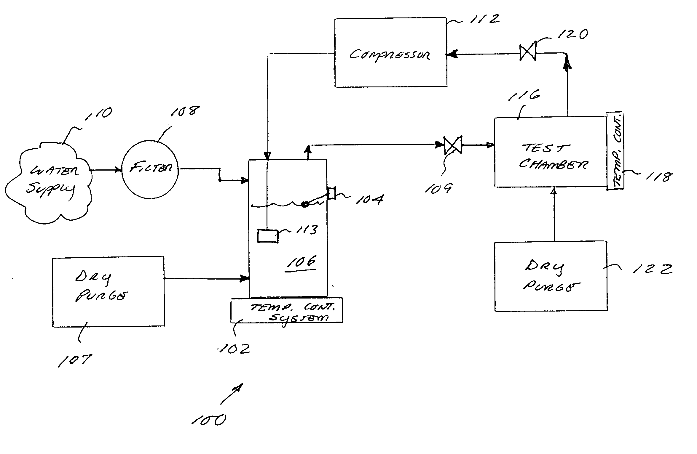
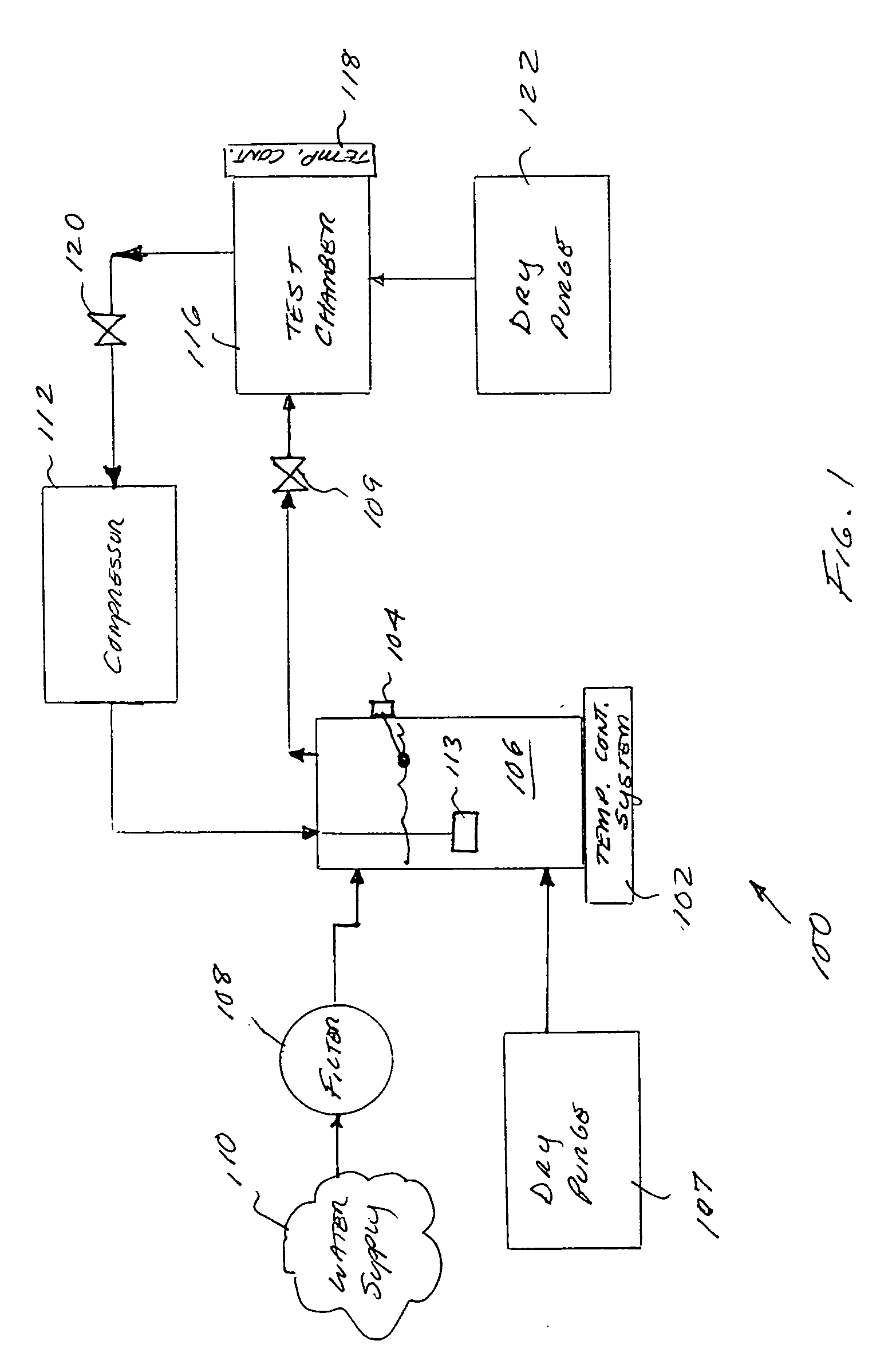
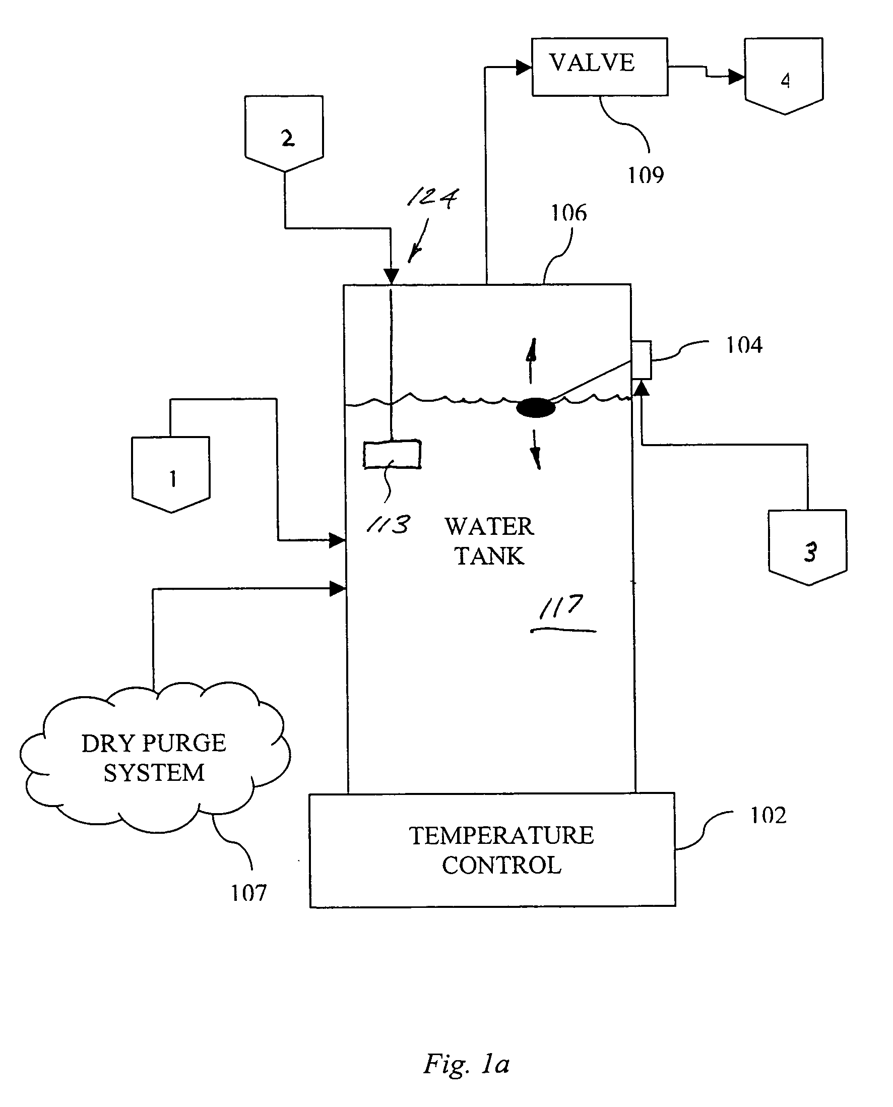
[0038] It is noted that while the following description is cast primarily in terms of an improved apparatus and method for use in controlling temperature and humidity within an enviro...


PUM


Abstract

A humidity control apparatus and methods for use with, e.g., an environmental test chamber. In one embodiment, the apparatus comprises a system having a test chamber, a water tank, motive source for a gaseous humidity carrier, and temperature controllers for the tank and chamber. The carrier gas (e.g., air) is diffused through the water tank, thereby saturating the gas to a prescribed humidity level. This saturated gas is then passed into the chamber, and the environment within the chamber (i.e., humidity and temperature) controlled by the controller(s) so as to maintain the desired humidity level. The apparatus disclosed has the primary advantage of reducing or even substantially eliminating condensation within the test chamber when humidity levels are increased.

Description

PRIORITY [0001] This application claims priority to U.S. provisional patent application Ser. No. 60 / 690,171 filed Jun. 13, 2005 of the same title, which is incorporated herein by reference in its entirety.COPYRIGHT [0002] A portion of the disclosure of this patent document contains material that is subject to copyright protection. The copyright owner has no objection to the facsimile reproduction by anyone of the patent document or the patent disclosure, as it appears in the Patent and Trademark Office patent files or records, but otherwise reserves all copyright rights whatsoever. [0003] 1. Field of the Invention [0004] This invention relates to environmental control in systems wherein a device under test (DUT) is conditioned. More particularly, this invention discloses a method and apparatus for producing a controllable change in humidity level at a temperature and saturation level that can be supported by the environment in which it is delivered. [0005] 2. Description of Related ...

Claims


Application Information

Patent Timeline
Patent Type & Authority Applications(United States)
IPC IPC(8): F24F3/14
CPCF24F3/14F24F11/0008G05D22/02G01R31/2881G01R31/2849
Inventor BASTON, COLIN
Owner SIGMA SYST
Why Eureka
Try Eureka