Rotational sensing with inductive sensor and rotating axial target surface

a technology of inductive sensor and target surface, applied in the field of rotational sensing, can solve the problems of emi (electromagnetic interference) in the rotational sensing system of stepper and other motor applications

Active Publication Date: 2015-11-12
TEXAS INSTR INC
View PDF0 Cites 13 Cited by
  • Summary
  • Abstract
  • Description
  • Claims
  • Application Information

AI Technical Summary

Benefits of technology

This patent describes how an inductive sensor works to detect changes in positioning of a moving object (such as a rotating shaft) based on its magnetic properties. By measuring these changes, the sensor produces a continuous signal that represents the movement of the object over time. In some cases, this signal has been found to be more accurate and reliable compared to traditional contact sensors used for similar applications. Additionally, the use of multiple sensors allows for better accuracy and reliability when detecting small amounts of change. Overall, this technology provides improved precision and efficiency for non-contact type motion detection systems.

Problems solved by technology

The technical problem addressed by this patent is how to provide reliable and accurate sensor feedback for controlling the operation of electrical motors, particularly those used in devices like steppers which rotate at high speeds. This is challenged because traditional position detection methods often experience interference from the strong magnetic fields generated by the motor's stator.

Method used


Image

  • Rotational sensing with inductive sensor and rotating axial target surface
  • Rotational sensing with inductive sensor and rotating axial target surface
  • Rotational sensing with inductive sensor and rotating axial target surface

Examples


Embodiment Construction

[0019]This Description and the Drawings constitute a Disclosure of example embodiments and applications that illustrate various features and advantages of rotational sensing with inductive sensor(s) and rotating axial target surface.

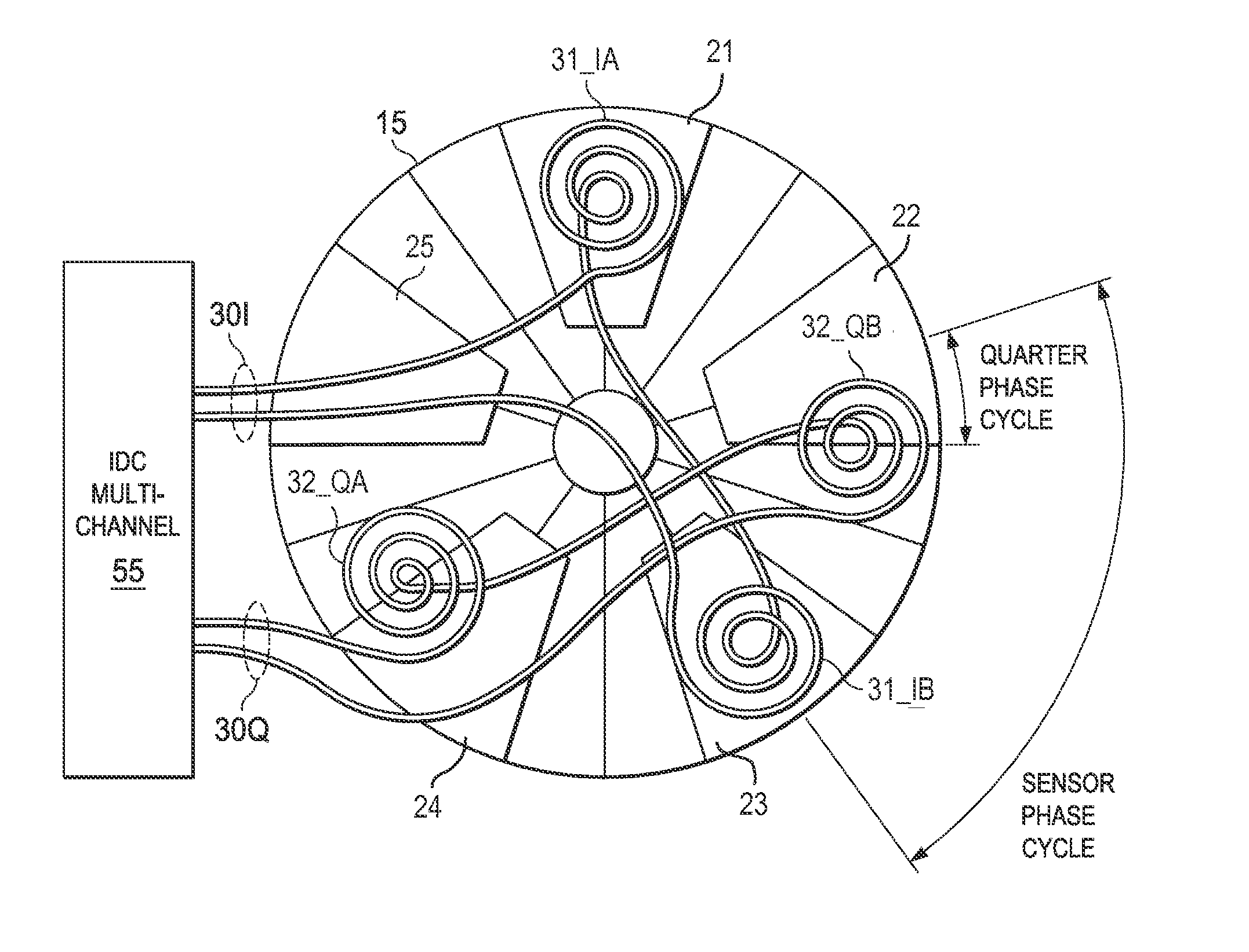
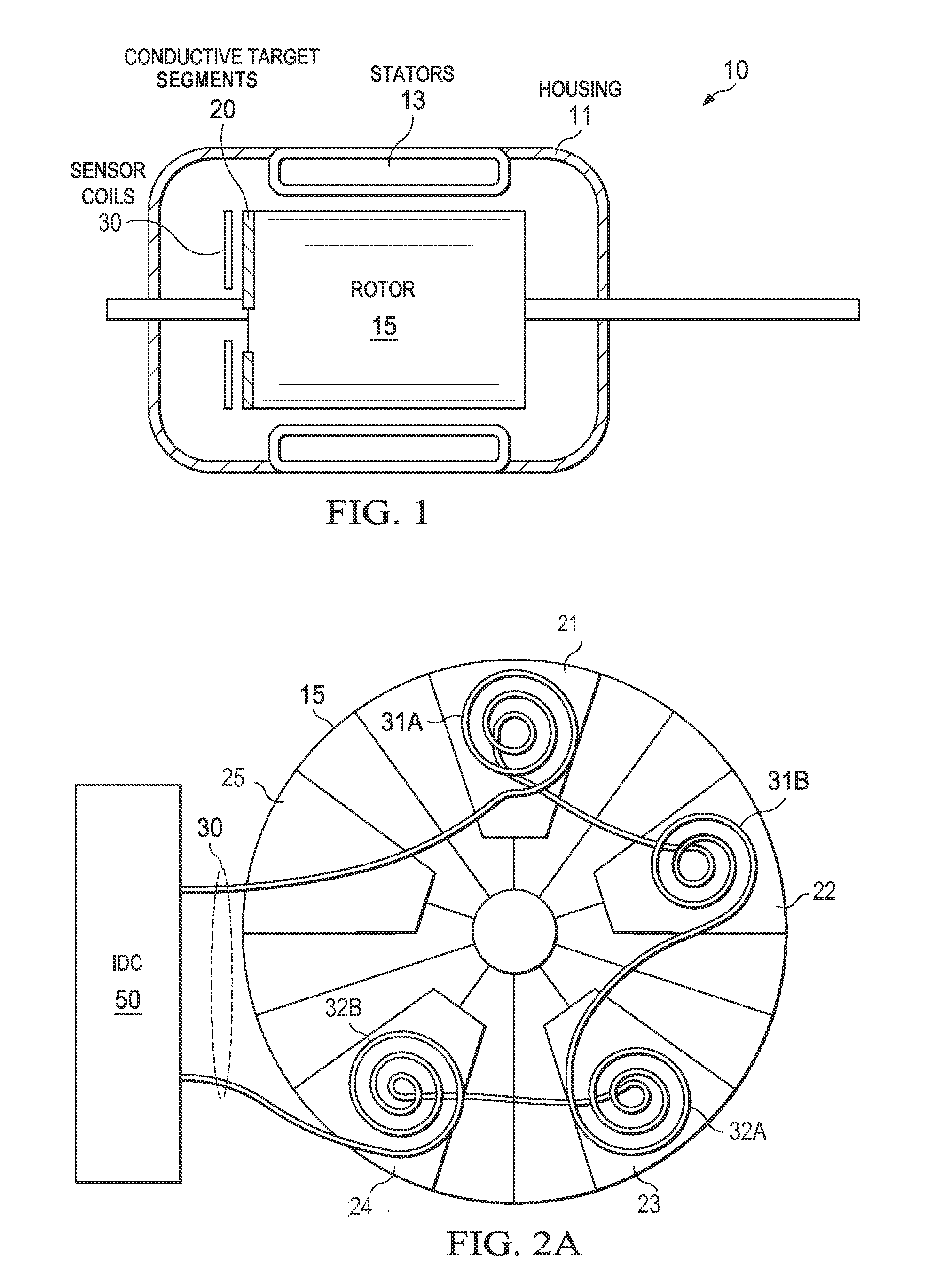
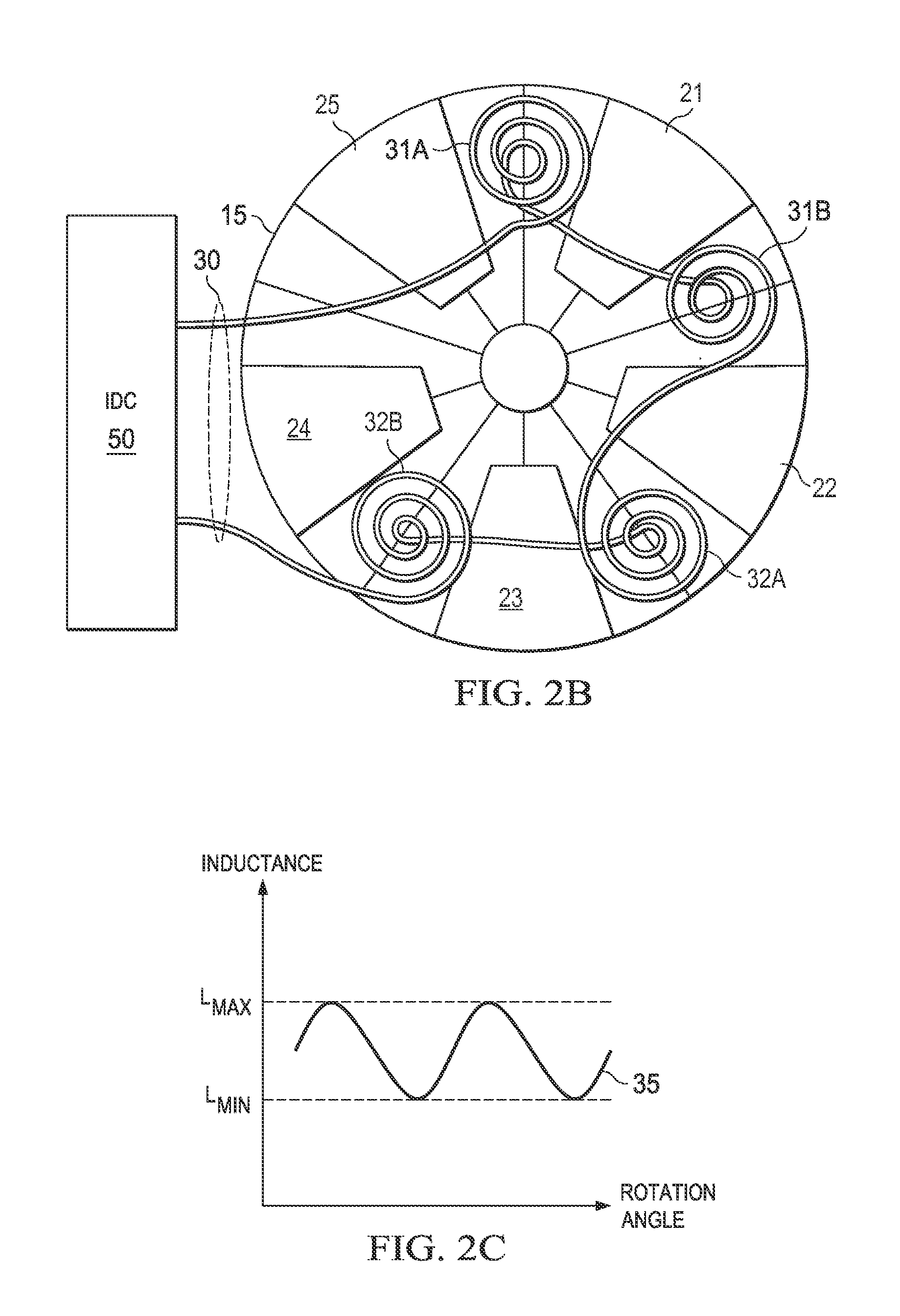
[0020]In brief overview, a rotational sensing system is adaptable to sensing motor rotation based on eddy current sensing. An axial target surface is mounted to the motor rotor, and includes one or more conductive target segment(s). An inductive sensor is mounted adjacent the axial target surface, and includes one or more inductive sense coil(s), such that rotor rotation rotates the target segment(s) laterally under the sense coil(s). An inductance-to-digital conversion (IDC) unit drives sensor excitation current to project a magnetic sensing field (B-field) toward the rotating axial target surface. Sensor response is characterized by successive sensor phase cycles that cycle between phase_cycle_LMIN in which a sense coil is aligned with a target segment...


PUM


Abstract

A rotational sensing system is adaptable to sensing motor rotation based on eddy current sensing. An axial target surface is incorporated with the motor rotor, and includes one or more conductive target segment(s). An inductive sensor is mounted adjacent the axial target surface, and includes one or more inductive sense coil(s), such that rotor rotation rotates the target segment(s) laterally under the sense coil(s). An inductance-to-digital converter (IDC) drives sensor excitation current to project a magnetic sensing field toward the rotating axial target surface. Sensor response is characterized by successive sensor phase cycles that cycle between LMIN in which a sense coil is aligned with a target segment, and LMAX in which the sense coil is misaligned. The number of sensor phase cycles in a rotor rotation cycle corresponds to the number of target segments. The IDC converts sensor response measurements from successive sensor phase cycles into rotational data.

Description


Claims


Application Information

Patent Timeline
Owner TEXAS INSTR INC
Why Eureka
Try Eureka