Marine Radar Based on Cylindrical Array Antennas with Other Applications

a technology of cylindrical arrays and radars, applied in the field of marine radars, can solve the problems of expensive operation and maintenance of radars

Inactive Publication Date: 2015-11-12
MARK RESOURCES
View PDF18 Cites 15 Cited by
  • Summary
  • Abstract
  • Description
  • Claims
  • Application Information

AI Technical Summary

Problems solved by technology

As a result, such radars are...

Method used


Image

  • Marine Radar Based on Cylindrical Array Antennas with Other Applications
  • Marine Radar Based on Cylindrical Array Antennas with Other Applications
  • Marine Radar Based on Cylindrical Array Antennas with Other Applications

Examples


Embodiment Construction

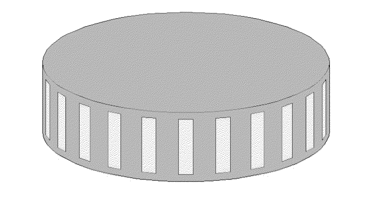
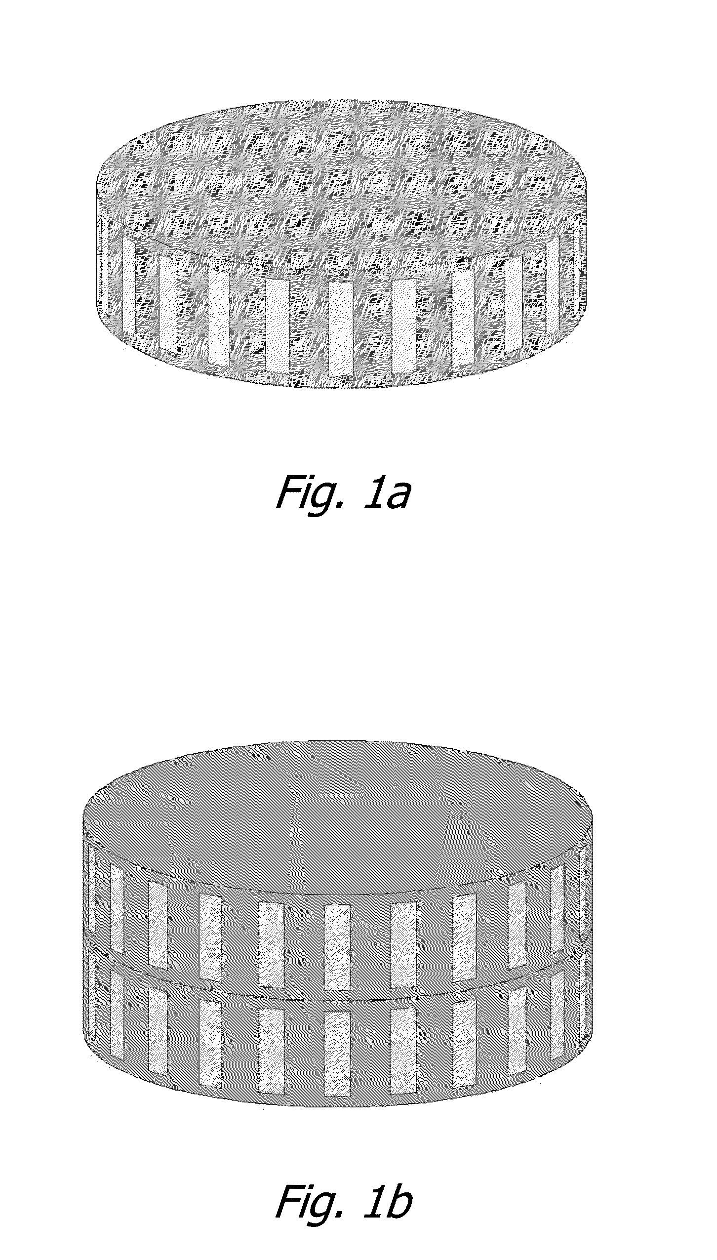
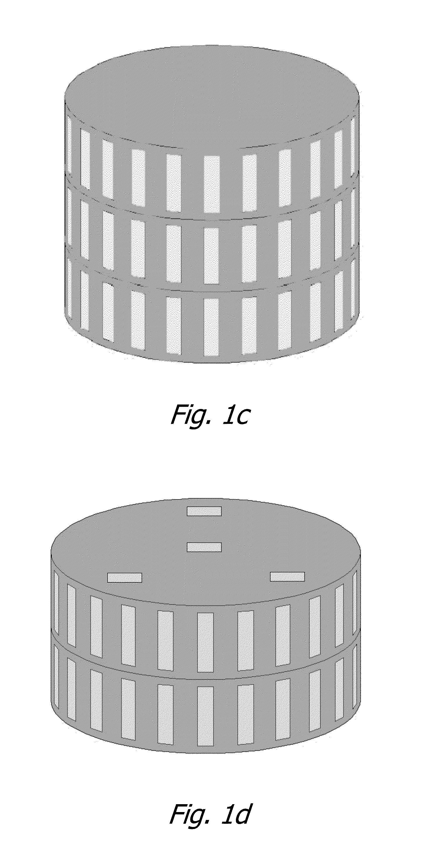
[0016]As mentioned before, marine radars commonly employ large mechanically rotating antennas to provide accurate bearing measurements, and also high-power magnetron transmitters to provide high detection sensitivity. As a result, such radars are expensive to operate and maintain. The present invention avoids these on-going expenses by using non-rotating antenna arrays and low-power solid-state electronics.

[0017]The present invention makes effective use of conventional radar technology, including an active array antenna utilizing a transmit / receive (T / R) module at each array element, pulse compression for achieving resolution in range, coherent processing for achieving resolution in Doppler, monopulse processing for measuring angles, discrimination of moving from stationary objects, mapping of terrain, tracking of all moving objects, and controlling the display on a computer monitor. Other embodiments, including continuous wave embodiments, are also disclosed.

Implementation of Conce...


PUM


Abstract

An all-solid-state marine radar technology based on a non-rotating cylindrical array antenna is described. Multiple transmit/receive (T/R) modules are used to form the antenna beam, which allows the beam sequencing, the dwell time in each beam position, the resolution, and the beam shape to be varied in order to make best use of the available energy. Waveforms with a high duty ratio can be used on transmit in order to make efficient use of solid-state power amplifiers. High resolution in both range and Doppler provides high measurement accuracy and superior performance in clutter. Alternate embodiments, including continuous waveform embodiments are disclosed.

Description

BACKGROUND OF THE INVENTION[0001]1. Field of the Invention[0002]The present invention relates to the field of marine radar for collision avoidance and navigation at sea, for locating navigation waypoints and hazards, for assessing wave conditions, and for monitoring ship traffic from a shore-based location. Related applications include surveillance of borders, harbors, coastlines, and secure facilities. An extension of the basic design provides surveillance of the airspace.[0003]2. Prior Art[0004]Marine radars commonly employ large mechanically rotating antennas to provide accurate bearing measurements, and also high-power magnetron transmitters to provide high detection sensitivity. As a result, such radars are expensive to operate and maintain.[0005]Some radars designed for other applications employ array antennas that can be electronically steered, avoiding the mechanical rotation mechanism. The modern version of the array antenna has independent transmit and receive capability a...

Claims


Application Information

Patent Timeline
IPC IPC(8): G01S13/02G01S13/937
CPCG01S13/02G01S7/032G01S13/91G01S2013/0245H01Q21/205G01S13/937G01S13/66
Inventor MITCHELL, RICHARD L.
Owner MARK RESOURCES
Why Eureka
Try Eureka