Boring Cutter

Inactive Publication Date: 2015-11-19
ZHUZHOU CEMENTED CARBIDE CUTTING TOOLS CO LTD
View PDF7 Cites 24 Cited by
  • Summary
  • Abstract
  • Description
  • Claims
  • Application Information

AI Technical Summary

Benefits of technology

[0014]Another advantage of the invention is to provide a boring cutter, wherein the discharging chambers are radially formed on the circumferential face of the tool body to communicate with the cooling channel via the fluid guiding grooves respectively. Therefore, during the drilling process, the cooling fluid is discharged from the cooling channel to the discharging chambers through the fluid guiding grooves respectively. The cooling fluid is then discharged at a gap between the tool body and the inner wall of the hole to form a dynamic cooling guidance, which can controllably adjust a pressure around the circumferential face of the tool body to minimize the tool deflection and drilling vibration. As a result, when drilling a deep hole, the co

Problems solved by technology

At the same time, the vibration is generated at a cutting end of the drilling tool is greater than that at the fitting portion, so as to cause the drilling related problems, such as the deflection of the drilling tool and drilling inefficiency.
As a result, the vibration at the cutting head will be increased to cause serious deflection of the drilling tool during

Method used


Image

  • Boring Cutter
  • Boring Cutter
  • Boring Cutter

Examples


Embodiment Construction

[0023]The following description is disclosed to enable any person skilled in the art to make and use the present invention. Preferred embodiments are provided in the following description only as examples and modifications will be apparent to those skilled in the art. The general principles defined in the following description would be applied to other embodiments, alternatives, modifications, equivalents, and applications without departing from the spirit and scope of the present invention.

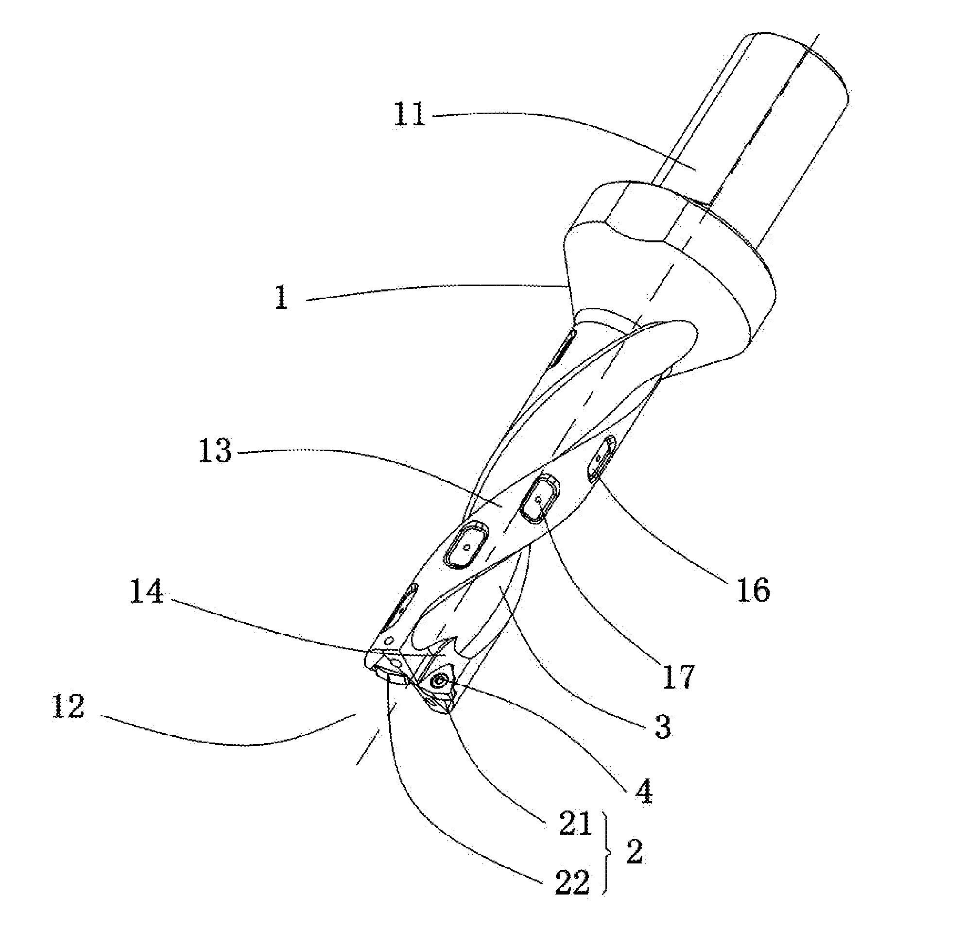
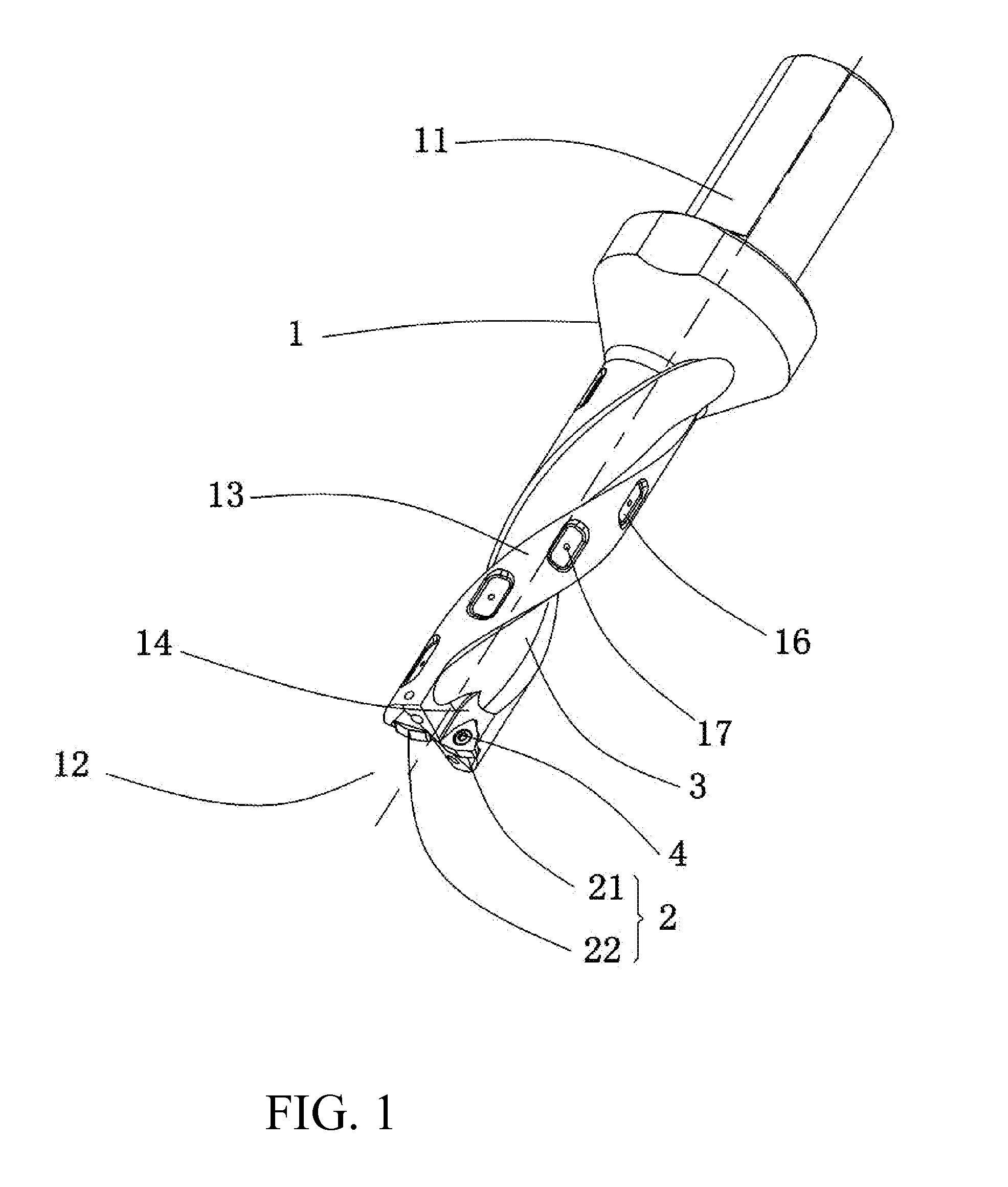
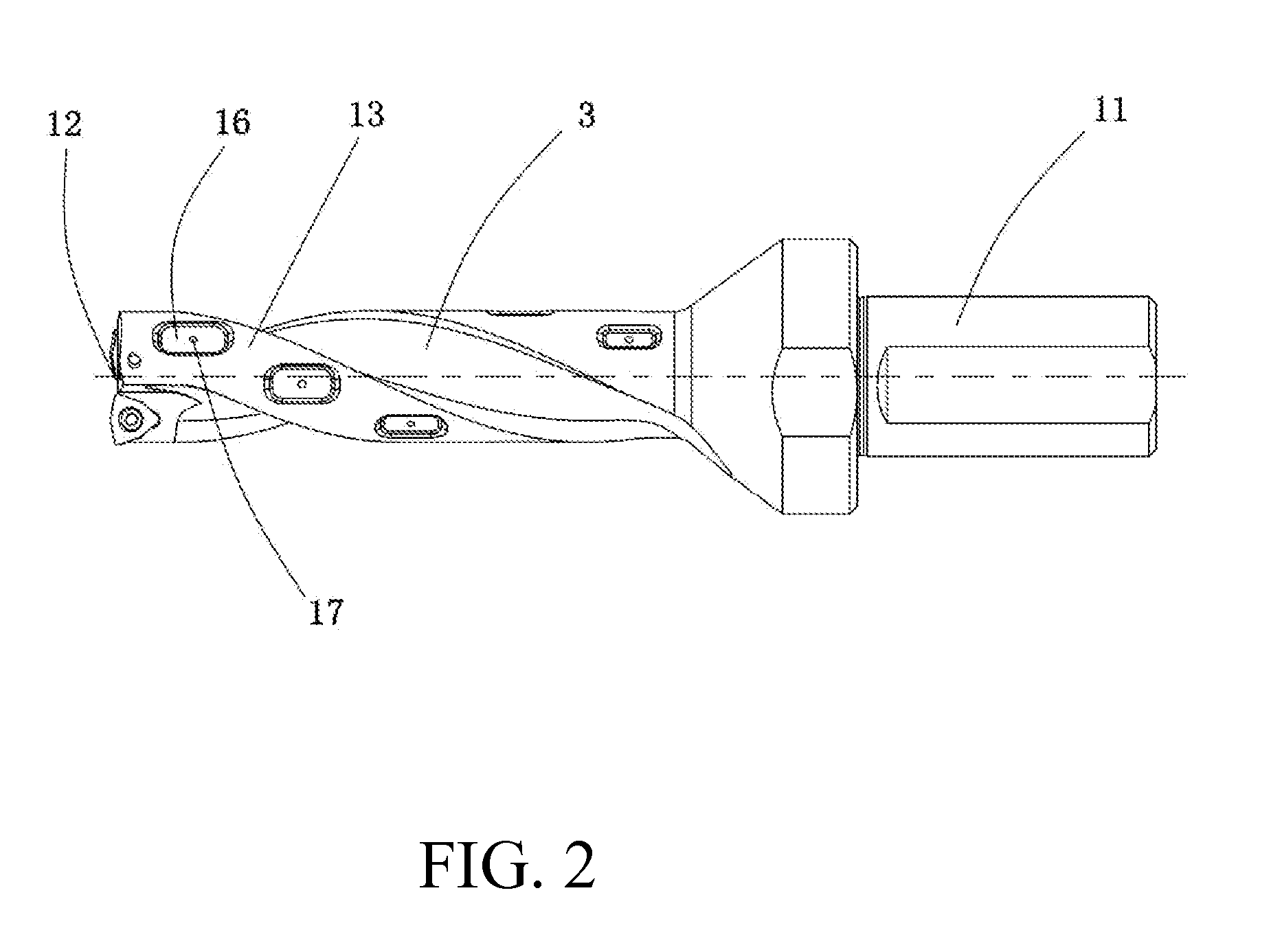
[0024]Referring to FIGS. 1 to 3, a boring cutter according to a preferred embodiment of the present invention is illustrated, wherein the boring cutter comprises a tool body 1, at least a cutting insert 2, and at least a fastener 4. The tool body 1 comprises a shaft handle 11 and a cutting end 12, and defines a circumferential face 13 extended between the shaft handle 11 and the cutting end 12. The tool body 1 further has at least an insert pocket 14 extending to the cutting end 12 in a helical m...


PUM

PropertyMeasurementUnit
Pressureaaaaaaaaaa
Angleaaaaaaaaaa
Sizeaaaaaaaaaa

Abstract

A boring cutter includes a tool body and a cutting insert. The tool body includes a shaft handle and a cutting end, and defines a circumferential face extended between the shaft handle and the cutting end. The tool body further has an insert pocket extended to the cutting end to secure the cutting insert at the insert pocket, and a flute formed on the circumferential face to communicate with the insert pocket. The tool body further has a cooling channel extended through the shaft handle to the cutting end, and a plurality of discharging chambers spacedly formed on the circumferential face to communicate with the cooling channel. During a drilling process, cooling fluid is released to the discharging chambers from the cooling channel to create a pressure between the tool body and an inner wall of a hole of a workpiece to prevent the tool deflection and drilling vibration.

Description

CROSS REFERENCE OF RELATED APPLICATION[0001]This is a non-provisional application that claims priority to international application number PCT / CN2013 / 084784, international filing date Sep. 30, 2013, which claims priority to Chinese application number 201310266451.5, filing date Jun. 28, 2013.NOTICE OF COPYRIGHT[0002]A portion of the disclosure of this patent document contains material which is subject to copyright protection. The copyright owner has no objection to any reproduction by anyone of the patent disclosure, as it appears in the United States Patent and Trademark Office patent files or records, but otherwise reserves all copyright rights whatsoever.BACKGROUND OF THE PRESENT INVENTION[0003]1. Field of the Invention[0004]The present invention relates to a tool, and more particular to a boring cutter which has a relatively large diameter size, an anti-vibration ability, and a high precision drilling structure.[0005]2. Description of Related Arts[0006]A drilling tool generally ...

Claims


Application Information

Patent Timeline
IPC IPC(8): B23B51/06B23B51/02
CPCB23B51/06B23B51/02Y10T408/45B23B2250/16B23B2251/50B23B2250/12B23B2251/408
Inventor WANG, SHEQUANJIANG, AISHENGTANG, AIMINLIU, MIN
Owner ZHUZHOU CEMENTED CARBIDE CUTTING TOOLS CO LTD
Why Eureka
Try Eureka