Tent system and methods

a technology of tents and tents, applied in tents/canopies, building types, constructions, etc., can solve the problems of not providing interior space, needlessly cumbersome and expensive tents, and difficulty in erecting, so as to reduce size, weight and cost, increase interior space, and facilitate set-up.

Inactive Publication Date: 2015-11-19
DRUMMOND DANIEL D
View PDF0 Cites 2 Cited by
  • Summary
  • Abstract
  • Description
  • Claims
  • Application Information

AI Technical Summary

Benefits of technology

[0003]The present invention provides a tent, which may be a beach tent, but could also be any other type of tent, featuring an elegant design that offers reduced size, weight, and cost, and increased interior space as compared to existing designs, while at the same time allowing for faster, easier set-up.
[0004]Current tents, including beach tents, use the spring of bent cross-members (rods or poles) to provide a force that stretches the floor (base) of the tent into a rigid shape, while at the same time providing support for the roof, which typically extends from the floor to the top of the tent, limiting interior head room throughout most of the tent. The improved tent of the present invention uses the geotechnical characteristics of the substrate on which tent is positioned (earth, snow, sand, etc.) to stretch the floor and to provide support for rigid vertical members (poles) that allow for substantially vertical construction and that can include corner-pole clips, each having a flange for tying, that hold the corners of the tent in place, preventing the corners from sliding up or down along their respective corner poles.

Problems solved by technology

Current beach tents are needlessly cumbersome and expensive, and are difficult to erect.
They tend to be hot, and they do not provide an interior space that people can comfortably use to change clothing and the like.

Method used


Image

  • Tent system and methods
  • Tent system and methods
  • Tent system and methods

Examples


Embodiment Construction

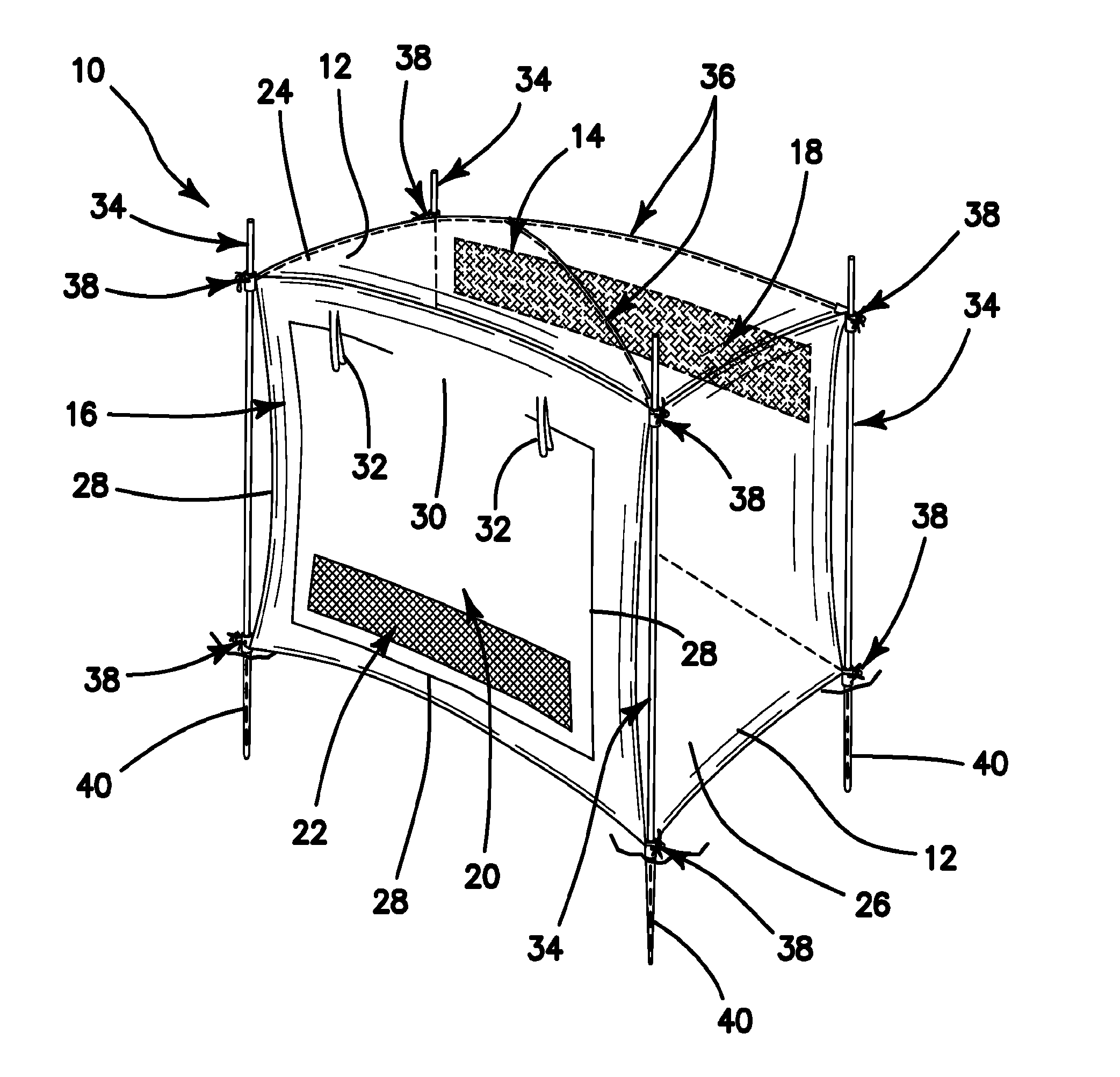
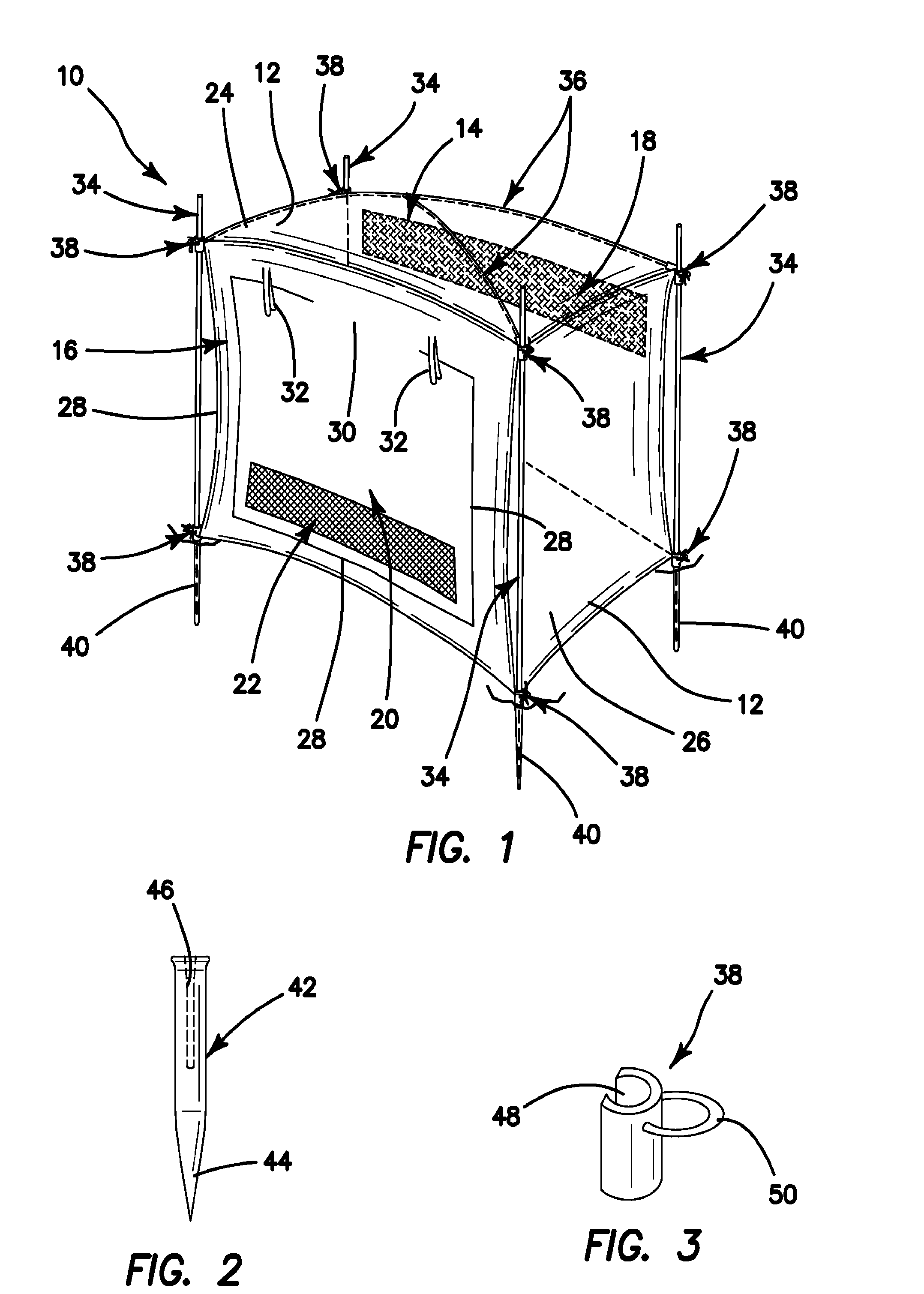
[0029]Referring now to FIGS. 1-3, there is shown in FIG. 1 a tent system 10 constructed in accordance with one particular embodiment of the present invention. The tent 10 comprises a plurality of side walls. As illustrated, the plurality of side walls comprise side walls 12, a rear wall 14, and a front wall 16. A screen window 18, which may be secured in an open or covered configuration, may be disposed on the rear wall 14, as shown. A zippered door 20 and a screen window 22 may be disposed on the front wall 16. The tent additionally includes a roof 24 and a floor 26. The door 20 may have a closure zipper 28, or other suitable closure means, extending about the lower three sides of the door 20, to open and close the door, about the top portion 30 which acts as a hinge. Ties 32 may be provided to tie the door 20 up in an open position.

[0030]The walls, ceiling, and floor of the tent are preferably constructed of a suitable fabric, which is preferably treated to be waterproof and UV ra...


PUM


Abstract

A tent has a floor, and a plurality of side walls connected to the floor. The tent additionally includes a plurality of external poles for supporting corners of the tent, and a clip attachable to at least one end of each external pole. The clip also includes a flange for attaching the clip to the tent side walls or floor. The system further includes a stake assembly for securing a lower end of each external pole directly into a ground surface on which the tent is disposed, which includes a sleeve portion having a linear channel for receiving a stake therethrough and a tent pole receptacle connected to the sleeve portion. The tent pole receptacle includes a channel for receiving a bottom end of a tent pole therein, wherein the stake assembly secures the tent pole disposed in the tent pole receptacle directly to the ground surface.

Description

BACKGROUND OF THE INVENTION[0001]Current beach tents are needlessly cumbersome and expensive, and are difficult to erect. They tend to be hot, and they do not provide an interior space that people can comfortably use to change clothing and the like.[0002]What is needed, therefore, is a new and innovative tent design which is inexpensive, easy to erect, and affords an interior space which is maximized in both area and height, while also being well supported against winds and other weather elements.SUMMARY OF THE INVENTION[0003]The present invention provides a tent, which may be a beach tent, but could also be any other type of tent, featuring an elegant design that offers reduced size, weight, and cost, and increased interior space as compared to existing designs, while at the same time allowing for faster, easier set-up.[0004]Current tents, including beach tents, use the spring of bent cross-members (rods or poles) to provide a force that stretches the floor (base) of the tent into ...

Claims


Application Information

Patent Timeline
Patent Type & Authority Applications(United States)
IPC IPC(8): E04H15/34E04H15/62E04H15/60
CPCE04H15/34E04H15/62E04H15/60E04H15/40
Inventor DRUMMOND, DANIEL D.
Owner DRUMMOND DANIEL D
Why Eureka
Try Eureka