Stations for Portable Electronic Devices

Inactive Publication Date: 2015-11-19
CLOUSER DOUG
View PDF35 Cites 10 Cited by
  • Summary
  • Abstract
  • Description
  • Claims
  • Application Information

AI Technical Summary

Benefits of technology

[0012]From the foregoing disclosure and the following more detailed description of various preferred embodiments it will be apparent to those skilled in the art that the present invention provides a significant advance in the technology and art of stations for portable electronic devices. Particularly significant in this

Problems solved by technology

With the increase in the number of available portable electronic devices, consumers can find themselves with an unpleasant and unsightly tangle of wires, cords, and/or cables for the devices.
In addition to the unsightly appearance, the tangled wires can be unsafe because kinked wires are more susceptible to failure and because it is difficult to identify a particu

Method used


Image

  • Stations for Portable Electronic Devices
  • Stations for Portable Electronic Devices
  • Stations for Portable Electronic Devices

Examples


first embodiment

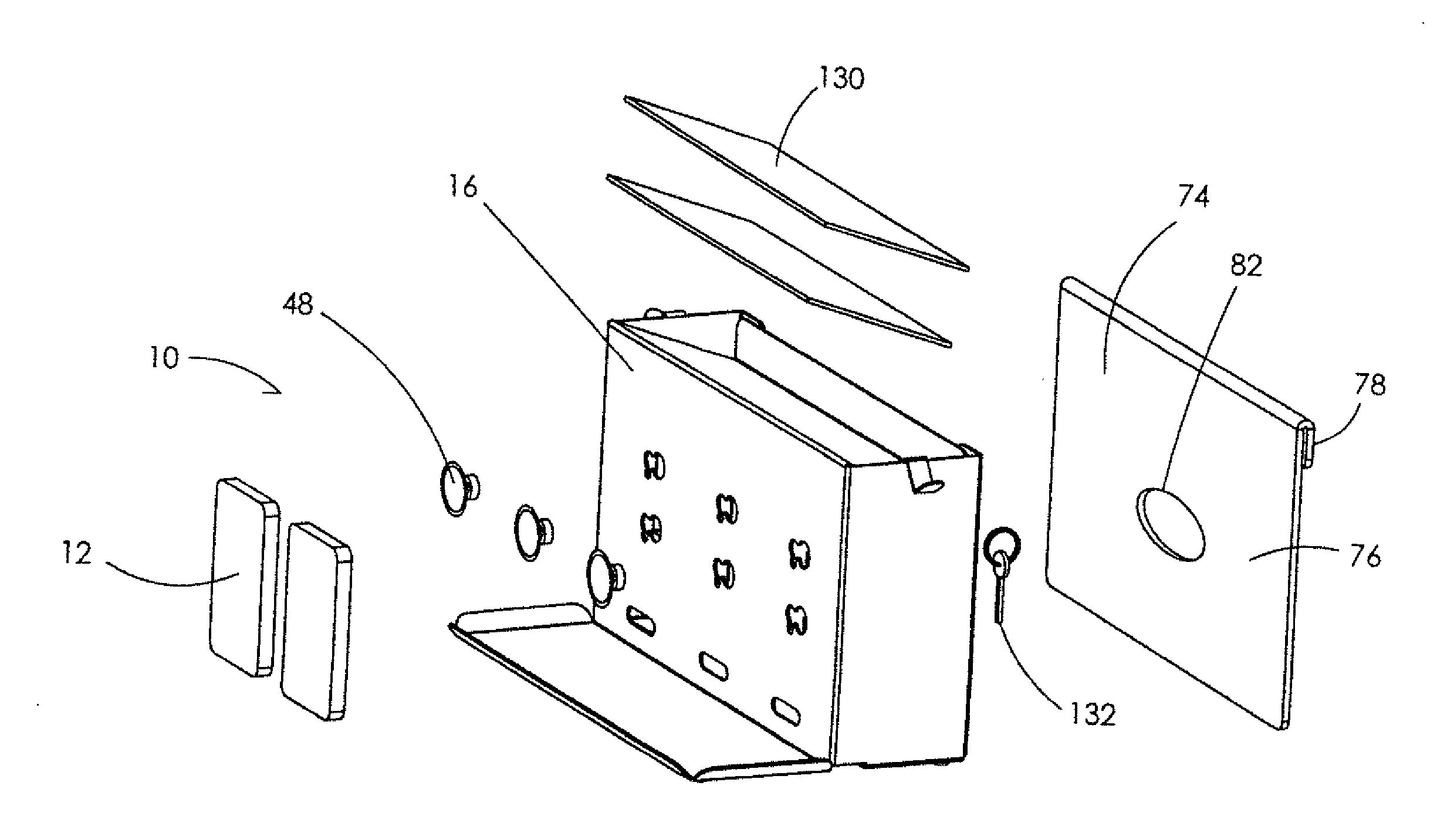
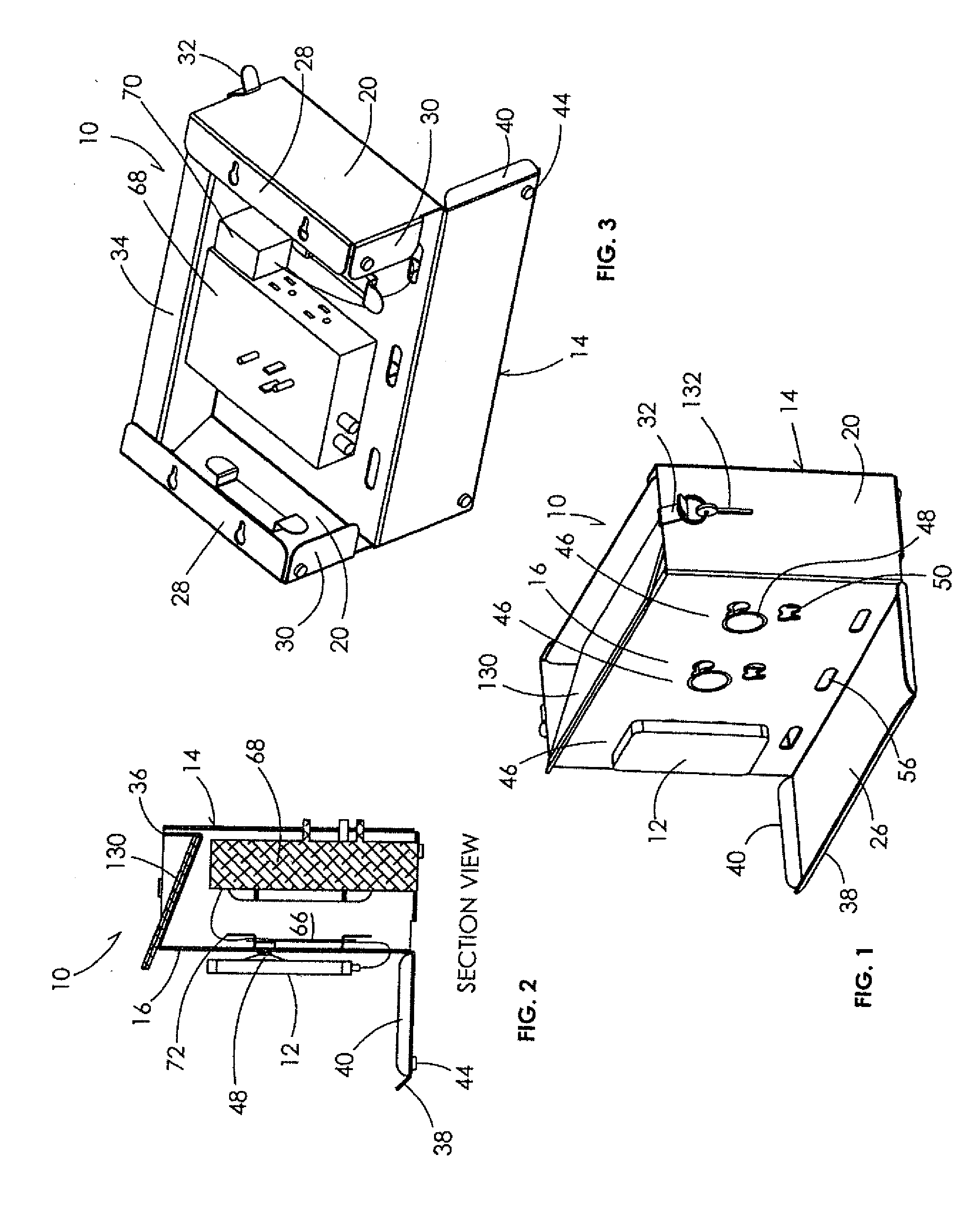
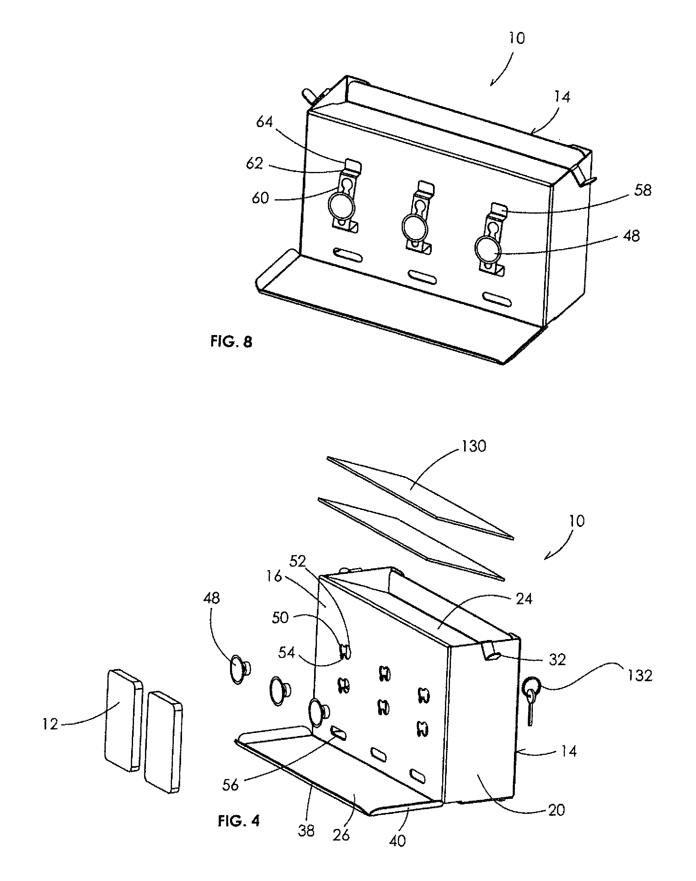
[0087]Referring now to the drawings, FIGS. 1 to 7 show a charging station 10 for a portable electronic device 12 according to the present invention. The illustrated charging station 10 includes a body or base 14 having a substantially vertical and forward-facing front wall 16 and a plurality of forward-facing fasteners 18 on the wall 16 so that the fasteners 18 can temporarily secure the portable electronic devices 12 to the wall 16 in a position that the portable electronic device can be viewed and operated while recharging. The fastener 18 is temporarily secured to the back of the portable electronic device 12 so that the portable electronic device 12 is held in a substantially vertical and forward-facing orientation so that it can be easily viewed and used while recharging and can be easily removed from the fastener 18 when recharging is complete. The illustrated fasteners 18 secure the portable electronic devices 12 against movement in three of the four primary directions within...

fourth embodiment

[0101]FIG. 15 illustrates a charging station 10 for a portable electronic device 12 according to the present invention. This embodiment further illustrates that the base 14 can take other forms. The illustrated base 14 is formed for use on a table top and has a substantially horizontal top wall 24, a substantially vertical back 98 wall downwardly-extending from the rear of the top wall 26 and provided with a rearwardly-extending horizontal flange 100 at its lower end, and a substantially vertical front wall 16 downwardly-extending from the front of the top wall 26 and provided with a forwardly-extending horizontal flange 102 at its lower end. The term “substantially vertical” is used to mean that the front wall 16 is no more than 45 degrees from vertical so that the portable electronic device 12 secured thereto can be easily used while recharging. The front wall 16 is provided with a single attachment location 46 for the portable electronic device 12 having a single opening 50 for t...

fifth embodiment

[0102]FIG. 16 illustrates a charging station 10 for a portable electronic device 12 according to the present invention. This embodiment further illustrates that the base 14 can take other forms and that the base 14 can be molded of a plastic. The illustrated base 14 forms a hollow interior for mounting over a wall electrical power outlet and includes a plurality of slots 104 for storing mail such as, for example, envelopes.

[0103]FIGS. 17 to 26 illustrate a variation of the charging station 10 of FIGS. 1 to 12. This variation of the charging station 10 is substantially the same except as described hereinbelow. This charging station 10 is provided with bottom supports or cradles 106 secured to the front wall 16 below the suction cups 48. The bottom supports 106 can limit downward movement of the portable electronic devices 12 if connections with the suction cup 48 inadvertently break or to provide additional support for the portable electronic device 12 when attached to the suction cu...


PUM


Abstract

A station for at least one portable electronic device includes a base having a substantially vertical and forward-facing wall and at least one suction cup secured to the wall to temporarily secure the portable electronic device to the wall in a position that the portable electronic device can be viewed and operated while secured to the wall. More than one suction cup can be provided to secure the portable electronic device to the wall.

Description

CROSS-REFERENCE TO RELATED APPLICATIONS[0001]This application is a continuation-in-part of U.S. patent application Ser. No. 14 / 327,862 filed on Jul. 10, 2014, which is a continuation-in-part of U.S. patent application Ser. No. 14 / 246,718 filed on Apr. 7, 2014, now abandoned, which is a continuation of U.S. patent application Ser. No. 13 / 190,251 filed on Jul. 25, 2011, issued as U.S. Pat. No. 8,692,511, which is a continuation-in-part of U.S. patent application Ser. No. 13 / 189,180 filed on Jul. 22, 2011, issued as U.S. Pat. No. 8,692,514, which claims priority from U.S. Provisional Patent Application No. 61 / 367,074 filed on Jul. 23, 2010, the disclosures of which are expressly incorporated herein in their entireties by reference.STATEMENT REGARDING FEDERALLY SPONSORED RESEARCH[0002]Not ApplicablePARTIES TO A JOINT RESEARCH AGREEMENT[0003]Not ApplicableREFERENCE TO APPENDIX[0004]Not ApplicableFIELD OF THE INVENTION[0005]The field of the present invention generally relates to docking o...

Claims


Application Information

Patent Timeline
IPC IPC(8): F16B47/00
CPCF16B47/003F16B21/09F16B47/00F16M11/041F16M11/08F16M13/022H02J7/0044
Inventor CLOUSER, DOUG
Owner CLOUSER DOUG
Why Eureka
Try Eureka