Adjusting device for an illumination component of a microscope, a microscope illumination device and a microscope

a technology for adjusting devices and microscopes, applied in the field of microscopy, can solve problems such as high cost, and achieve the effects of eliminating the requirement, reducing the cost of equipment and rack parts, and reducing the cost of equipment and equipmen

Active Publication Date: 2015-11-19
LEICA MICROSYST LTD SHANGHAI SHANGHAI
View PDF6 Cites 10 Cited by
  • Summary
  • Abstract
  • Description
  • Claims
  • Application Information

AI Technical Summary

Benefits of technology

[0004]The present invention provides a simpler, more cost-effective adjusting device for an illumination component of a microscope, an microscope illumination device and a microscope containing the adjusting device.
[0013]According to one embodiment, the second end of each set screw is made of material which provides friction and has resiliency.
[0028]According to one embodiment, the first end of at least one of the plurality of set screws has a head which protrudes from the side wall of the first barrel component to facilitate manual adjustment.
[0035]With the adjusting device, the illumination device or the microscope including the adjusting device according to embodiments of the present invention, due to elimination of gear and rack parts of a traditional adjusting device, the structure of the present invention is simpler, more convenient to machine, and eliminates the requirement on the attachment face, thereby needing less space and lower cost. In addition, since a nylon head is utilized by the set screws as a friction means in some embodiments, the risk of the outside wall of the barrel component being scratched is reduced. Furthermore, in some embodiments, the adjusting device may comprise a support arm one end of which when in use is secured to the first barrel component and the other end is secured to the main body of a microscope to support the adjusting device, therefore the adjusting device integrates two functions of supporting the illumination component and moving the condenser.

Problems solved by technology

But the rack structure occupies a larger space, and imposes a high requirement on the attachment face, thereby resulting in a higher cost.

Method used


Image

  • Adjusting device for an illumination component of a microscope, a microscope illumination device and a microscope
  • Adjusting device for an illumination component of a microscope, a microscope illumination device and a microscope
  • Adjusting device for an illumination component of a microscope, a microscope illumination device and a microscope

Examples


Embodiment Construction

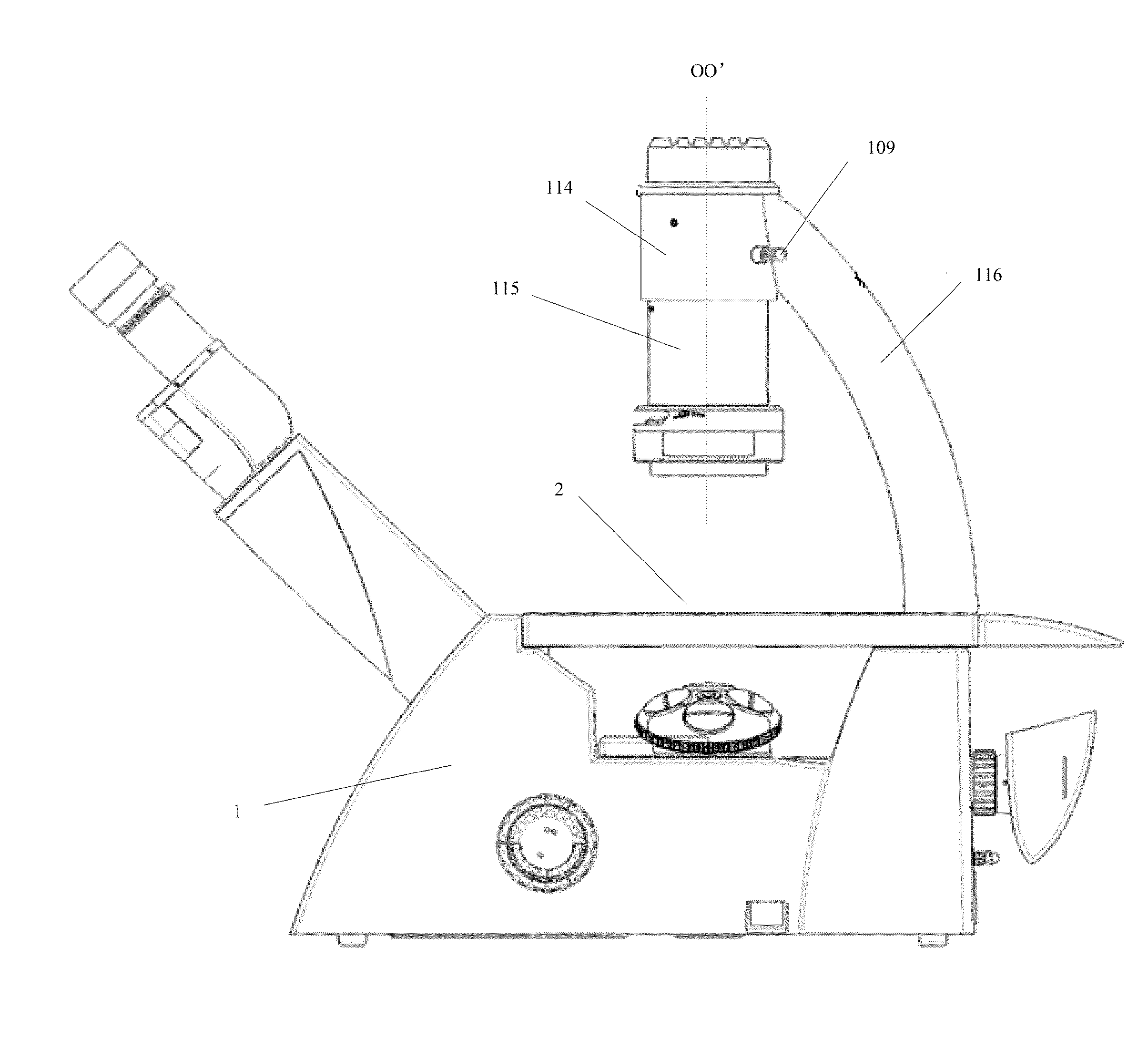
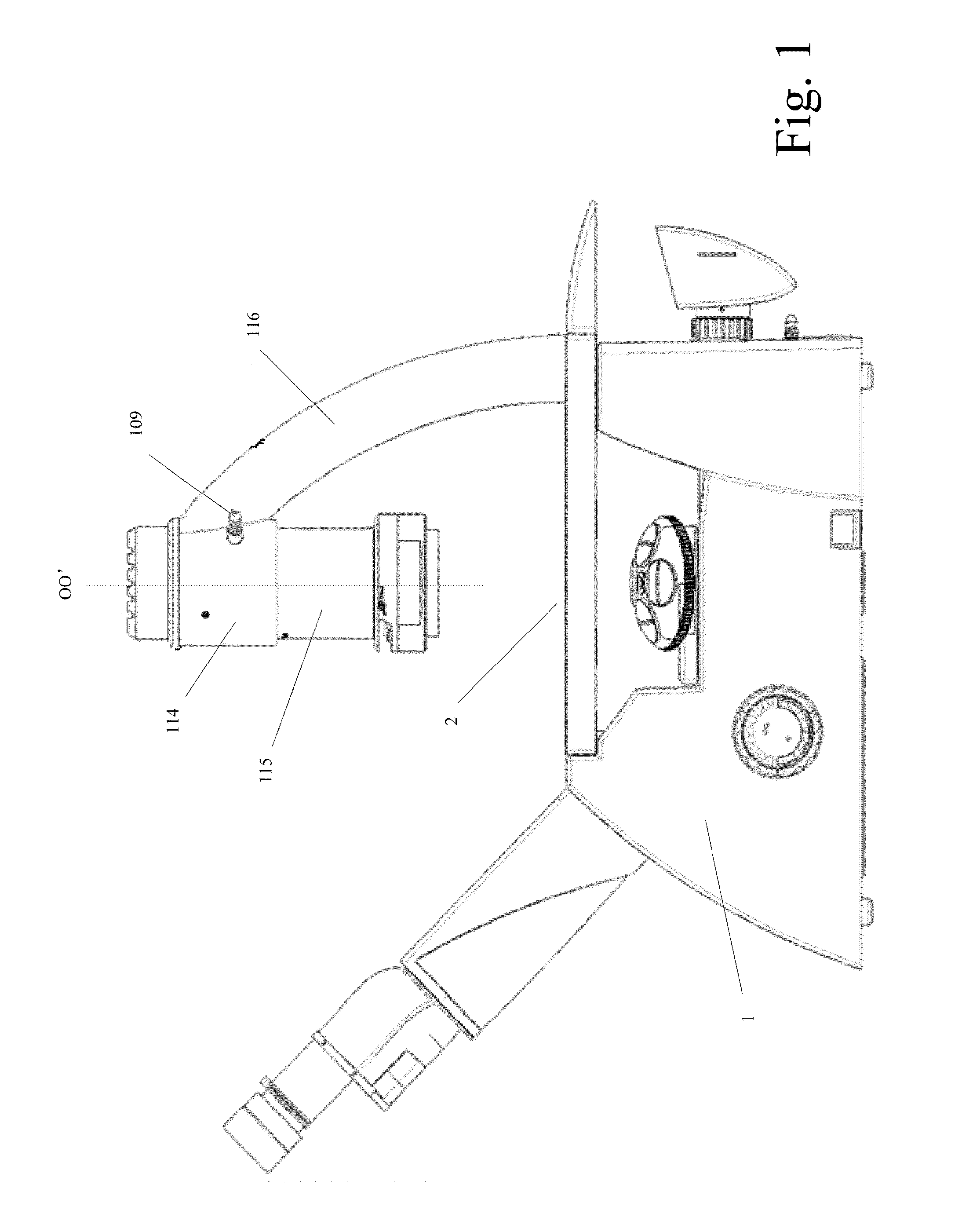
[0041]FIG. 1 shows a microscope including an illumination component contained in an adjusting device. FIG. 1 shows two constituent parts of the adjusting device: a first barrel component 114 and a second barrel component 115. Wherein, the second barrel component 115 for housing and supporting the illumination component is encased in the first barrel component, and their respective axes coincide with or are parallel to each other. In respective embodiments of FIG. 1 and the following, for the sake of brief, the axes OO′ of the first barrel component 114 and the second barrel component 115 are described and shown as coinciding with each other. In use, the illumination component is secured to the second barrel component 115 and is contained in the space inside the second barrel component 115. Also shown in FIG. 1 is a support arm 116, one end of which is secured to the first barrel component 114, and when in use, the other end is secured to the main body 1 of the microscope, such that ...


PUM


Abstract

An adjusting device for an illumination component of a microscope, an illumination device and a microscope containing the adjusting device are disclosed. The adjusting device for an illumination component of a microscope includes a first barrel component having an axis; a second barrel component received in the first barrel component, the second barrel component having an axis coincident with or parallel to the axis of the first barrel component, wherein the second barrel component houses and supports the illumination component; and a plurality of set screws each having a first end coupled to a side wall of the first barrel component at a corresponding coupling point and a second end pressed against a side wall of the second barrel component. With embodiments of the present invention, the structure is simpler and the cost is lower.

Description

CROSS-REFERENCE TO RELATED APPLICATIONS[0001]This application claims priority of Chinese patent application number 201420242651.7 filed May 13, 2014, the entire disclosure of which is incorporated by reference herein.TECHNICAL FIELD[0002]The present invention relates to the field of microscopy, and more particularly to an adjusting device for an illumination component of a microscope, a microscope illumination device and a microscope containing the adjusting device.BACKGROUND OF THE INVENTION[0003]In general, a microscope includes an illumination component for illuminating the object to be observed placed on the table of the microscope, for example, a condenser. Generally, the illumination component can be adjusted through an adjusting device so as to condense the light to a desired position. Typically, the movement of the illumination component is achieved using a rack structure. But the rack structure occupies a larger space, and imposes a high requirement on the attachment face, ...

Claims


Application Information

Patent Timeline
Patent Type & Authority Applications(United States)
IPC IPC(8): G02B21/06
CPCG02B21/06G02B21/0088G02B21/24
Inventor QIAN, CHRISDONG, GLORIA
Owner LEICA MICROSYST LTD SHANGHAI SHANGHAI
Why Eureka
Try Eureka