Display substrate and method of manufacturing the same

Inactive Publication Date: 2015-11-19
SAMSUNG DISPLAY CO LTD
View PDF4 Cites 11 Cited by
  • Summary
  • Abstract
  • Description
  • Claims
  • Application Information

AI Technical Summary

Benefits of technology

[0031]According to a present exemplary embodiment, a shielding electrode is entirely formed on a light-blocking region, so that a black matrix ma

Problems solved by technology

However a CRT display apparatus is relatively large and not very portable.
Thus, a parasitic capacitance m

Method used


Image

  • Display substrate and method of manufacturing the same
  • Display substrate and method of manufacturing the same
  • Display substrate and method of manufacturing the same

Examples


Example

[0044]Hereinafter, exemplary embodiments of the present inventive concept will be explained in detail with reference to the accompanying drawings.

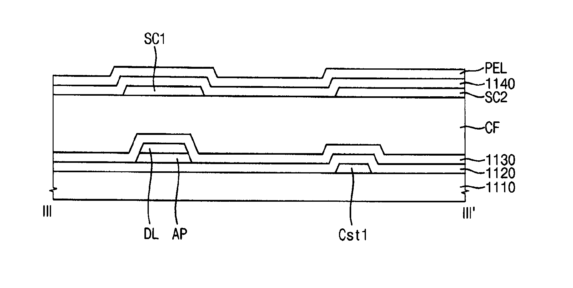
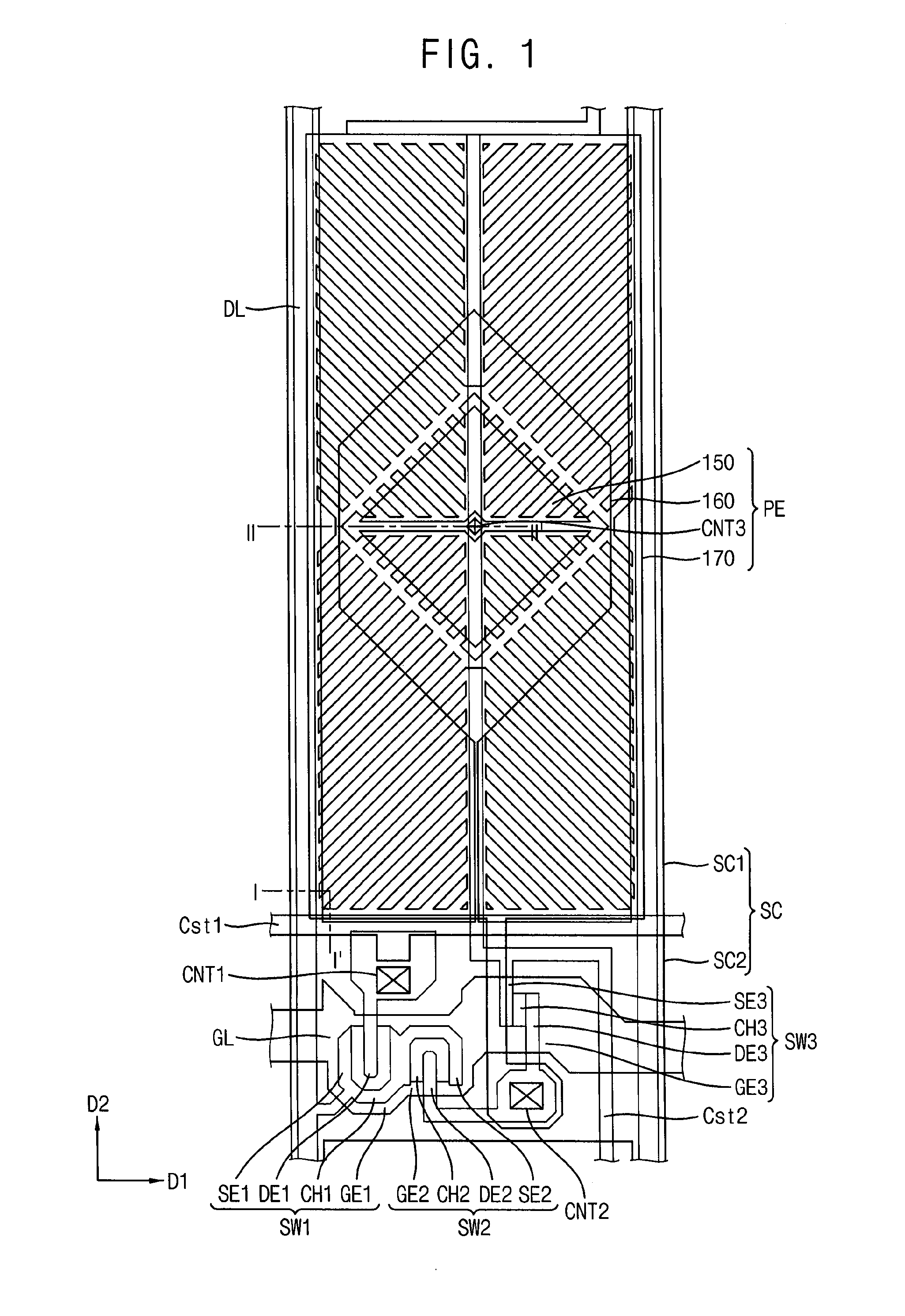
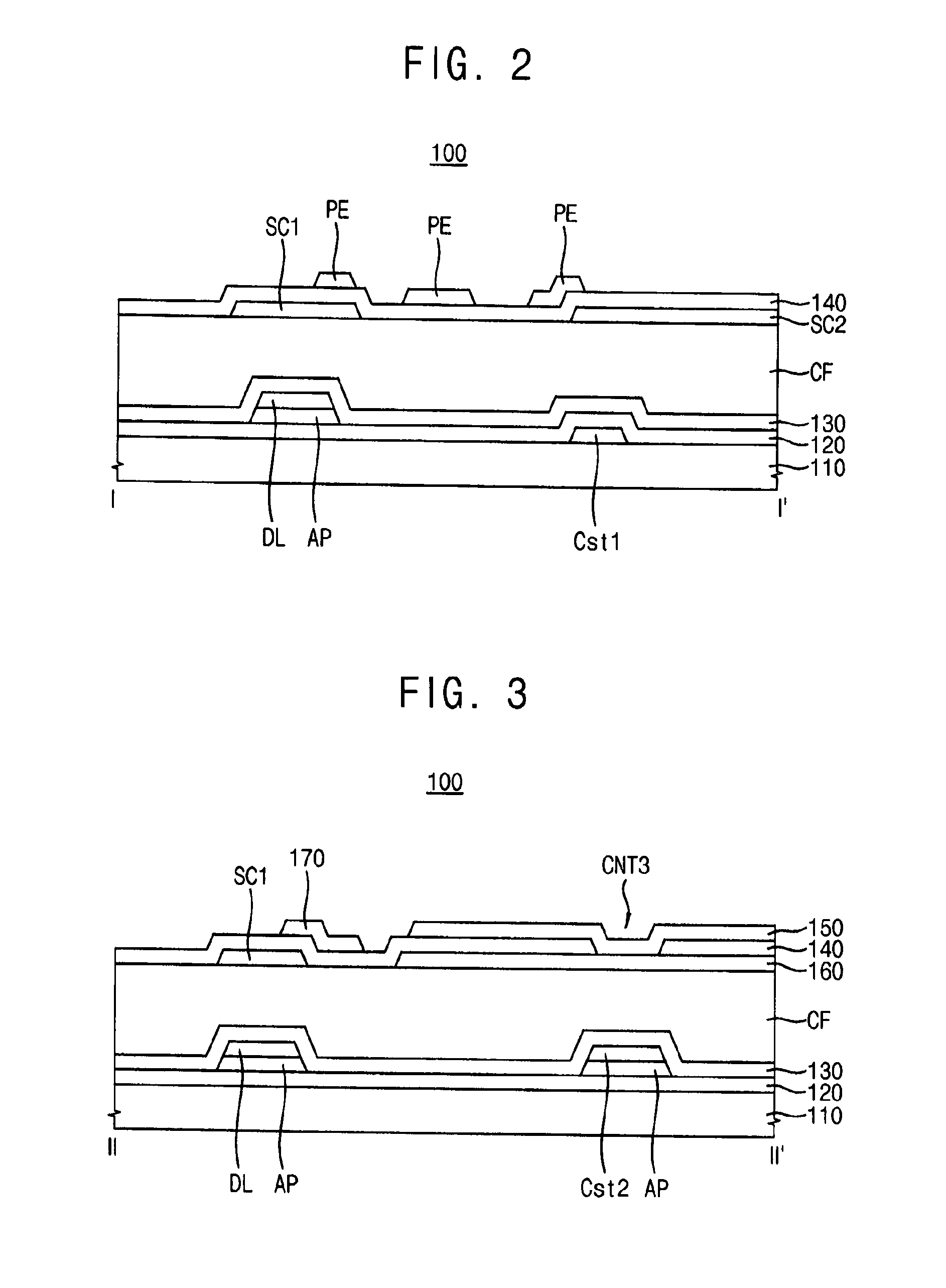
[0045]FIG. 1 is a plan view of a display substrate according to an exemplary embodiment of the inventive concept. FIG. 2 is a cross-sectional view taken along a line I-I′ of FIG. 1. FIG. 3 is a cross-sectional view taken along a line II-II′ of FIG. 1.

[0046]Referring to FIGS. 1 to 3, a display substrate 100 includes a gate line GL, a data line DL, a first storage line Cst1, a second storage line Cst2, a first switching element SW1, a second switching element SW2, a third switching element SW3, a shielding electrode SC, and a pixel electrode PE. The pixel electrode PE may include a first sub-pixel electrode 150, a second sub-pixel electrode 160 and a third sub-pixel electrode 170.

[0047]The gate line GL extends in a first direction D1. The gate line GL may have a single layer structure that may include copper (Cu), silver (Ag), chrome (Cr), m...


PUM


Abstract

A display substrate includes a first switching element electrically connected to a gate line and that extends in a first direction and electrically connected to a data line that extends in a second direction crossing the first direction, an insulation layer disposed on the first switching element, a shielding electrode disposed on the insulation layer and a pixel electrode that partially overlap the shielding electrode. The shielding electrode includes a first portion that overlaps the data line and extends in the second direction and a second portion that overlaps the gate line and extends in the first direction.

Description

PRIORITY STATEMENT[0001]This application claims priority under 35 U.S.C. §119 from Korean Patent Application No. 10-2014-0058094, filed on May 15, 2014 in the Korean Intellectual Property Office KIPO, and all the benefits accruing therefrom, the contents of which are herein incorporated by reference in their entirety.BACKGROUND[0002]1. Technical Field[0003]Embodiments of the present inventive concept are directed to a display substrate and method of manufacturing the display substrate. More particularly, embodiments of the present inventive concept are directed to a display substrate for a liquid crystal display and method of manufacturing the display substrate.[0004]2. Discussion of the Related Art[0005]Recently, a liquid crystal display apparatus having light weight and small size has been manufactured. A cathode ray tube (CRT) display apparatus has been used in the past due to performance and a competitive price. However a CRT display apparatus is relatively large and not very po...

Claims


Application Information

Patent Timeline
IPC IPC(8): G02F1/1368H01L29/66H01L29/786G02F1/1362H01L27/12
CPCG02F1/1368G02F1/13624H01L27/124H01L27/1259G02F2001/136218H01L29/78693H01L29/78669H01L29/66969H01L29/66765H01L27/1248H01L29/41733H01L27/1225G02F1/136218G02F1/134345G02F1/133345G02F1/134309G02F1/136286G02F2201/123H01L27/1222H01L27/1262
Inventor KANG, JANG-MIJUNG, MEE-HYEHWANG, IN-JAEKIM, SUNG-HWANKIM, IL-GONLIM, SUNG-UK
Owner SAMSUNG DISPLAY CO LTD
Why Eureka
Try Eureka