Magnetic Inductive Coil Module

Pending Publication Date: 2021-03-25
PIN SHINE INDAL
View PDF0 Cites 1 Cited by
  • Summary
  • Abstract
  • Description
  • Claims
  • Application Information

AI Technical Summary

Benefits of technology

[0015]The second coil set is made by molding or stamping. This can decrease manufacturing costs and is easy to implement. The second coil set is formed by integratedly connecting the first winding body and the second winding body. This simplifies the assembling process. Especially for the connection with an external circuit, what is needed is to connect the first conductive portion to the second conductive portion. This reduces possibility of blind joint and increases reliability.
[0016]The isolation frame is sandwiched by the second coil set. This is advantageous to the coating of the isolation layer. The isolation frame is provided with a positioning trough corresponding to both the first winding body and the second winding body in contour for alignment and

Problems solved by technology

1. Printing two coils on a printed circuit board is so complicated and difficult and such a transformer possesses a small withstand current. As a result, costs of such a transformer is too high and is hard to have competitiveness in the market.
2. Insulative paint is painted between the two coils for isolation. It is hard to meet the requirements of safety of transformers so as to make transformers easy to be damaged. Especially for step-down transformers connecting mains electricity, the voltage across their primary coils is high, so isolation between a primary coil and a secondary coil must be good enough.
3. When assembling a magnetic core, a central magnetic column of the magnetic core must pass assembling holes reserved in each coil. Alignment of these assembling holes must be very accurate, otherwise assembling difficulty will rise or the gap between the coil and the magnetic core will be too large. Automatic mass production is hard to be implemented.
1. Isolation with safe distance between planar coils lacks. As abovementioned, even

Method used


Image

  • Magnetic Inductive Coil Module
  • Magnetic Inductive Coil Module
  • Magnetic Inductive Coil Module

Examples


Embodiment Construction

[0025]The invention provides a magnetic inductive coil module which can serve as an inductor or a transformer.

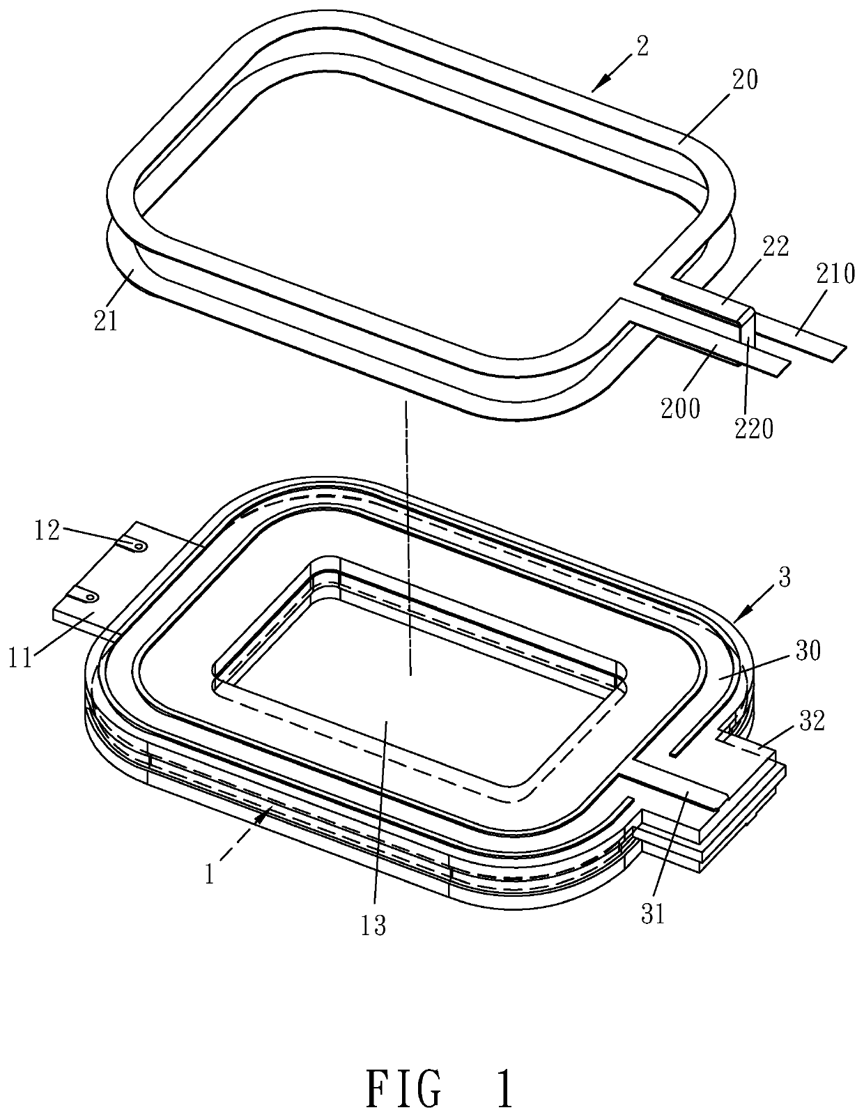
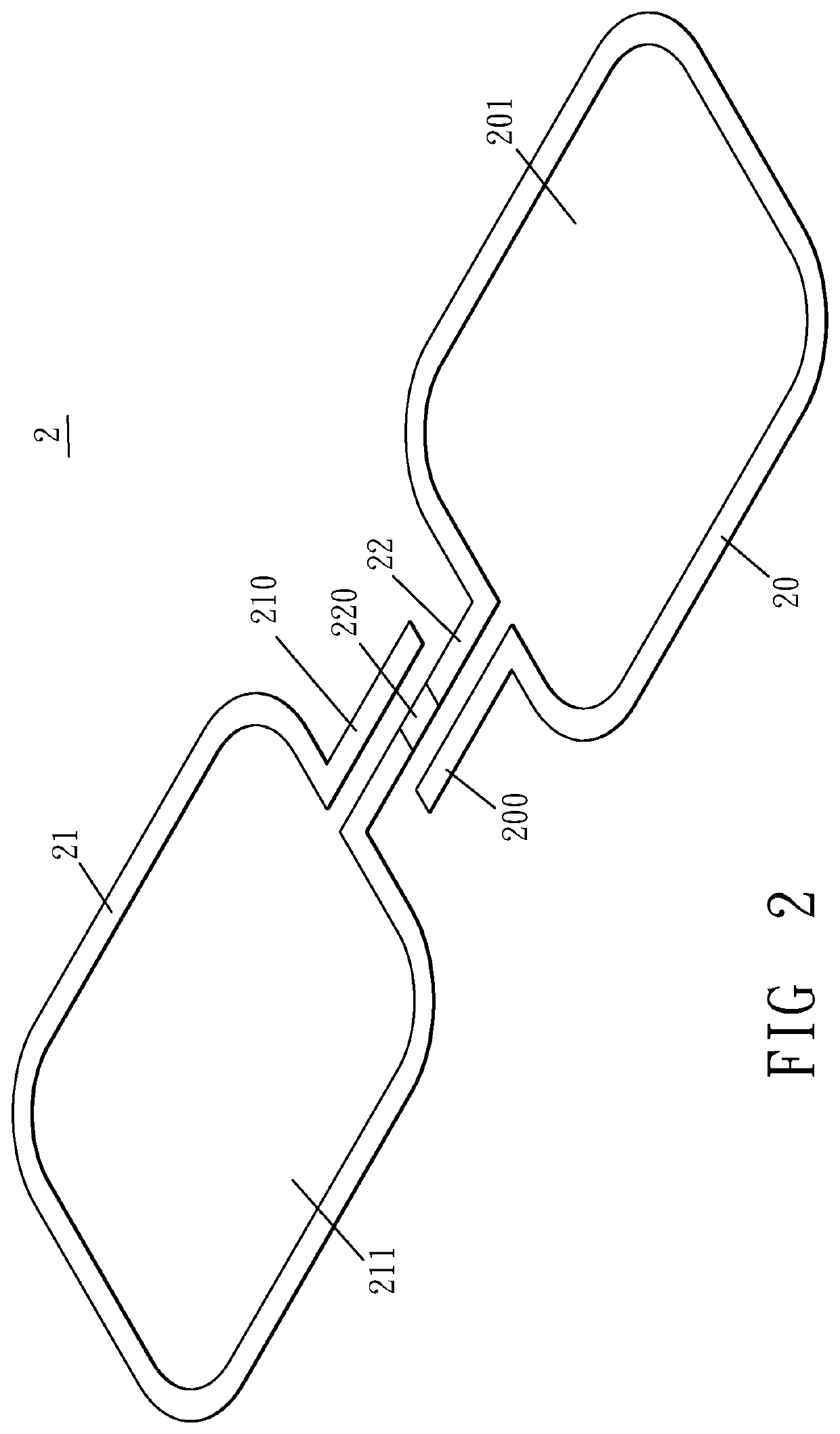
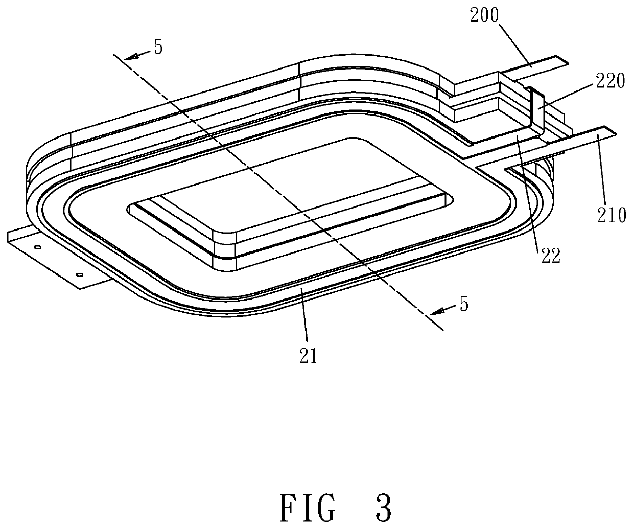
[0026]Please refer to FIGS. 1-5. The invention includes a first coil set 1 and a second coil set 2. The outside of the first coil set 1 has an isolation frame 3. The second coil set 2 is attached on two opposite sides of the isolation frame 3 to form a coil module as shown in FIGS. 3 and 4.

[0027]Please refer to FIGS. 1 and 5. The first coil set 1 is a conductive pattern 10 disposed on an insulative substrate 11. For example, the conductive pattern 10 is printed on a printed circuit board (PCB) to form the first coil set 1. Another available way is to lay the conductive pattern 10 on the insulative substrate 11. In addition, a side of the insulative substrate 11 may be provided with contacts 12 connected with the conductive pattern 10 for connecting an external circuit. An inner hole 13 is formed in the first coil set 1 for receiving a magnetic core of a transformer.

[0028]The...


PUM


Abstract

A coil module includes a first coil set and a second coil set. The first coil set has an isolation frame. The second coil set has an open first winding body. The first winding body has two ends which are out of contact with each other. One of the two ends has a first conductive portion projecting from the first winding body. The other one of the two ends has a connecting end from which an open second winding body is integratedly outward extended. A terminal of the second winding body has a second conductive portion which is outward protrudent. The connecting end comprises a bent portion which makes the second winding body and the first winding body arranged in the same direction so that the second winding body and the first winding body are attached on two opposite sides of the isolation frame.

Description

TECHNICAL FIELD[0001]The invention relates to coil modules, particularly to inductive elements such as inductors or transformers.RELATED ART[0002]Magnetic inductive elements such as transformers must have two independent coils, i.e., a primary coil and a secondary coil. Voltages across the two coils can be transformed in a turn ratio of the two coils according to the electromagnetic induction principle.[0003]In actual applications, a transformer is usually mounted on an independent insulative base. The insulative base is provided with conductive pins for connecting the coils with an external circuit. Also, the insulative base can serve as signal isolation to prevent interference.[0004]With the trend of compactness of customer electronics, transformers also become thinner and lighter. Known prior art has provided a planar transformer formed by printing two coil-shaped patterns to serve as two coils on a printed circuit board. In manufacture, such a planar transformer still has drawba...

Claims


Application Information

Patent Timeline
IPC IPC(8): H01F27/30H01F27/32H01F27/28H01F27/29
CPCH01F27/306H01F27/324H01F2027/2809H01F27/29H01F27/2804H01F27/2847H01F27/303H01F27/323H01F2027/2814H01F2027/2861
Inventor LIN, CHIH-HUNGCHANG, KUN-CHUAN
Owner PIN SHINE INDAL
Why Eureka
Try Eureka