
Catalytic converter and fabrication method thereof

Active Publication Date: 2012-12-20
HYUNDAI MOTOR CO LTD
View PDF9 Cites 1 Cited by
  • Summary
  • Abstract
  • Description
  • Claims
  • Application Information

AI Technical Summary

Benefits of technology

[0015]Various aspects of the present invention provide for a catalyst unit having advantages of decreasing a manufacturing cost by saving a noble metal.
[0040]As described, the edge portion except the central portion of the front surface of the carrier is easily plugged in the catalyst unit and the manufacturing method thereof according to the present invention.
[0041]Further, the channel corresponding to dead zone that the exhaust gas hardly flow is plugged by plugs and the catalyst coating layer is not formed in the plugged channels. Accordingly, the cost of the catalyst can be saved, and the purification rate of the exhaust gas is securely maintained by closing the channels that the exhaust gas flow is less.

Problems solved by technology

Meanwhile, a noble metal is coated in the whole carrier regardless of flow characteristic of exhaust gas when manufacturing the catalyst carrier, wherein there is a problem that a noble metal is not efficiently used according to the flow characteristic of the exhaust gas.

Method used


Image

  • Catalytic converter and fabrication method thereof
  • Catalytic converter and fabrication method thereof
  • Catalytic converter and fabrication method thereof

Examples


Embodiment Construction

[0060]Reference will now be made in detail to various embodiments of the present invention(s), examples of which are illustrated in the accompanying drawings and described below. While the invention(s) will be described in conjunction with exemplary embodiments, it will be understood that present description is not intended to limit the invention(s) to those exemplary embodiments. On the contrary, the invention(s) is / are intended to cover not only the exemplary embodiments, but also various alternatives, modifications, equivalents and other embodiments, which may be included within the spirit and scope of the invention as defined by the appended claims.

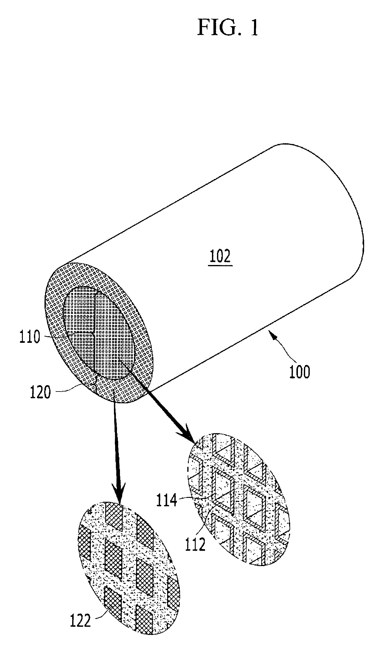
[0061]FIG. 1 is a schematic perspective view of a catalyst unit according to various embodiments of the present invention.

[0062]Referring to FIG. 1, a catalyst unit 100 includes a carrier 102.

[0063]The carrier 102 has an overall cylindrical shape, and channels 112 are formed from a front surface to a rear surface such that exhaust gas...


PUM

PropertyMeasurementUnit
Lengthaaaaaaaaaa
Thicknessaaaaaaaaaa
Distanceaaaaaaaaaa

Abstract

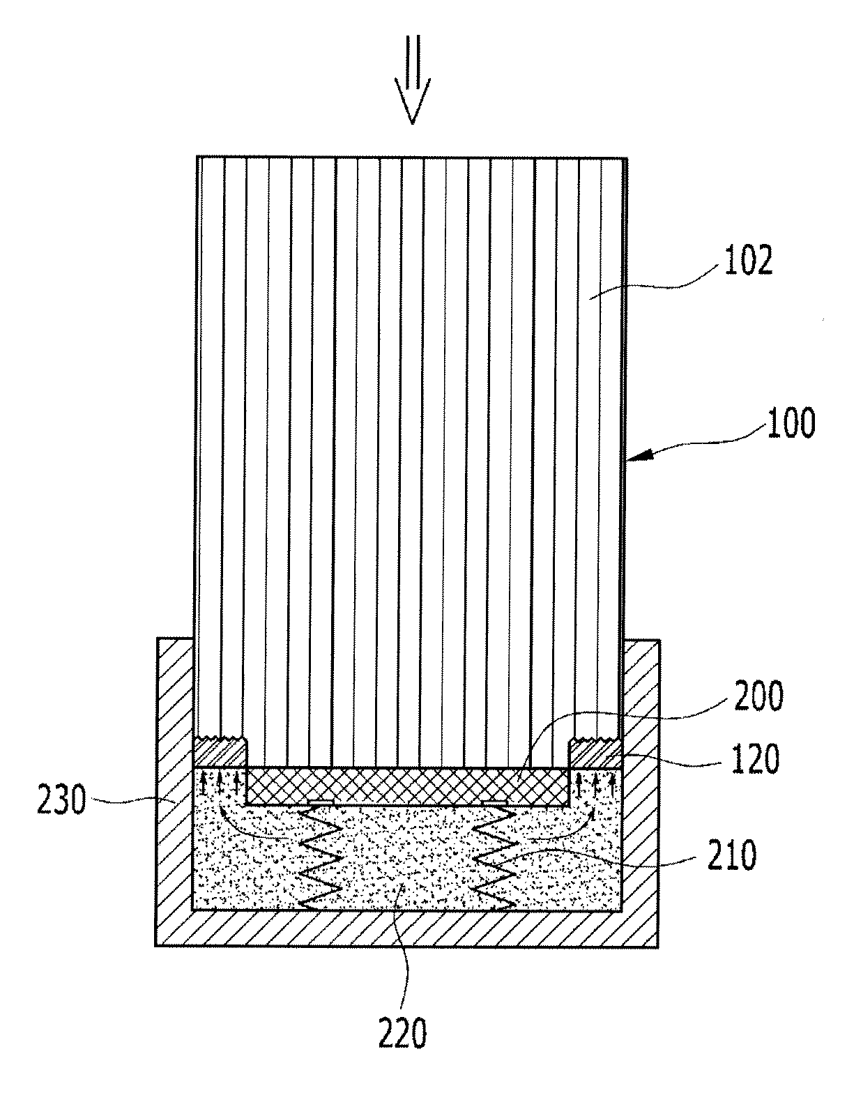
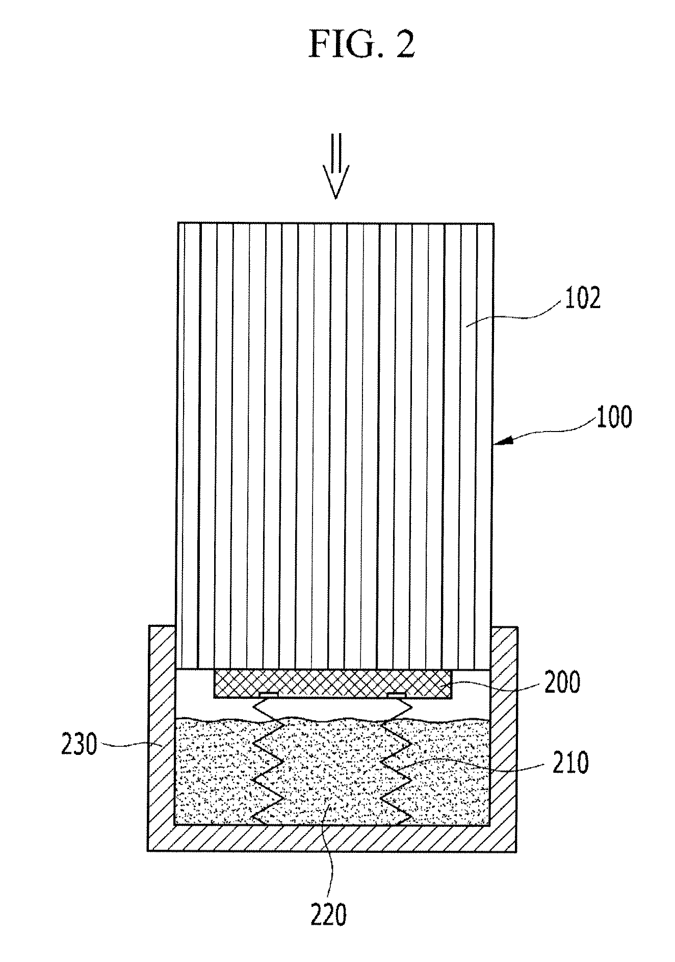
A catalyst unit may include a carrier, a channel opening portion through which exhaust gas passes, a skin portion that is formed along a circumference and integrally formed with the channel opening portion, and a skin addition portion that is formed with a second thickness on an outside surface of the skin portion. A fabrication device of the catalyst unit may include a container, a masking member, and an elastic member, wherein plugging material flows through opened channels and does not contact the masking member. A manufacturing method of the catalyst unit may include covering the masking member and inserting plugging material into an opened channel. A channel corresponding to a dead zone is plugged and the catalyst coating layer is not formed in the plugged channels, thus reducing the cost of the catalyst.

Description

CROSS-REFERENCE TO RELATED APPLICATION[0001]This application claims priority to and the benefit of Korean Patent Application Nos. 10-2011-0059211, 10-2011-0061775, and 10-2011-0061774 filed in the Korean Intellectual Property Office on Jun. 17, 2011, Jun. 24, 2011, and Jun. 24, 2011, respectively, the entire contents of which applications is incorporated herein for all purposes by this reference.BACKGROUND OF INVENTION[0002]1. Field of Invention[0003]The present invention relates to a catalyst unit that includes catalyst ingredients to reduce harmful materials of exhaust gas according to a flow characteristic.[0004]2. Description of Related Art[0005]In a vehicle, a three way catalyst converter is generally used to purify exhaust gas, which is disposed on an exhaust pipe, and the specifications thereof are different, because exhaust gas flow rates are different according to vehicles.[0006]The three way catalytic converter simultaneously reacts harmful materials of exhaust gas such as...

Claims


Application Information

Patent Timeline
IPC IPC(8): B32B3/20B29C43/18
CPCF01N3/2825F01N3/0222Y02T10/20Y10T428/13B01D46/2459Y10T428/24744B28B11/007B29C57/10B29D99/0089Y02T10/12B01D46/2482B01D46/2462
Inventor CHOI, SUNGMU
Owner HYUNDAI MOTOR CO LTD
Learn More