
Sensor Arrangements

a technology of sensors and luminaires, applied in the field of smart luminaires, can solve the problems of poor aesthetic appearance, difficult decoration and cleaning, and the data collected by the thermostat is limited to the immediate environment of its location, and achieves the effects of simple and less expensive manufacturing, high granularity, and usefulness

Active Publication Date: 2015-11-26
GOOEE
View PDF6 Cites 67 Cited by
  • Summary
  • Abstract
  • Description
  • Claims
  • Application Information

AI Technical Summary

Benefits of technology

The invention is about creating new luminaire components that have sensors to collect information about their environment and communicate it to a processor. This offers a way to gather data about the environment in which the luminaire is placed. Compared to dedicated sensors, the new luminaires have better granularity and are more useful. The use of wireless communication protocols between the sensors and the luminaire makes it easier to design and manufacture. The new technology also allows for the incorporation of various sensor technologies into the luminaire without needing a wired connection between them. The patent text also mentions environmental controllers that interact with the lighting environment in smart-homes and automated environments. These include RGB lighting controllers, rotary lighting dimmers, lighting scene controllers, and specialist lighting controls.

Problems solved by technology

This means that data gathered by the thermostat is limited to the immediate environment of its location.
This poses a problem for providing power to the sensor and obtaining data from the sensor, particularly where the light fitting needs to be IP (Ingress Protection) rated or fire rated.
It also means that the sensor or sensors are highly visible on an outer surface of the luminaire, leading to a poor aesthetic appearance and presents difficulties for decoration and cleaning.

Method used


Image

  • Sensor Arrangements
  • Sensor Arrangements
  • Sensor Arrangements

Examples


Embodiment Construction

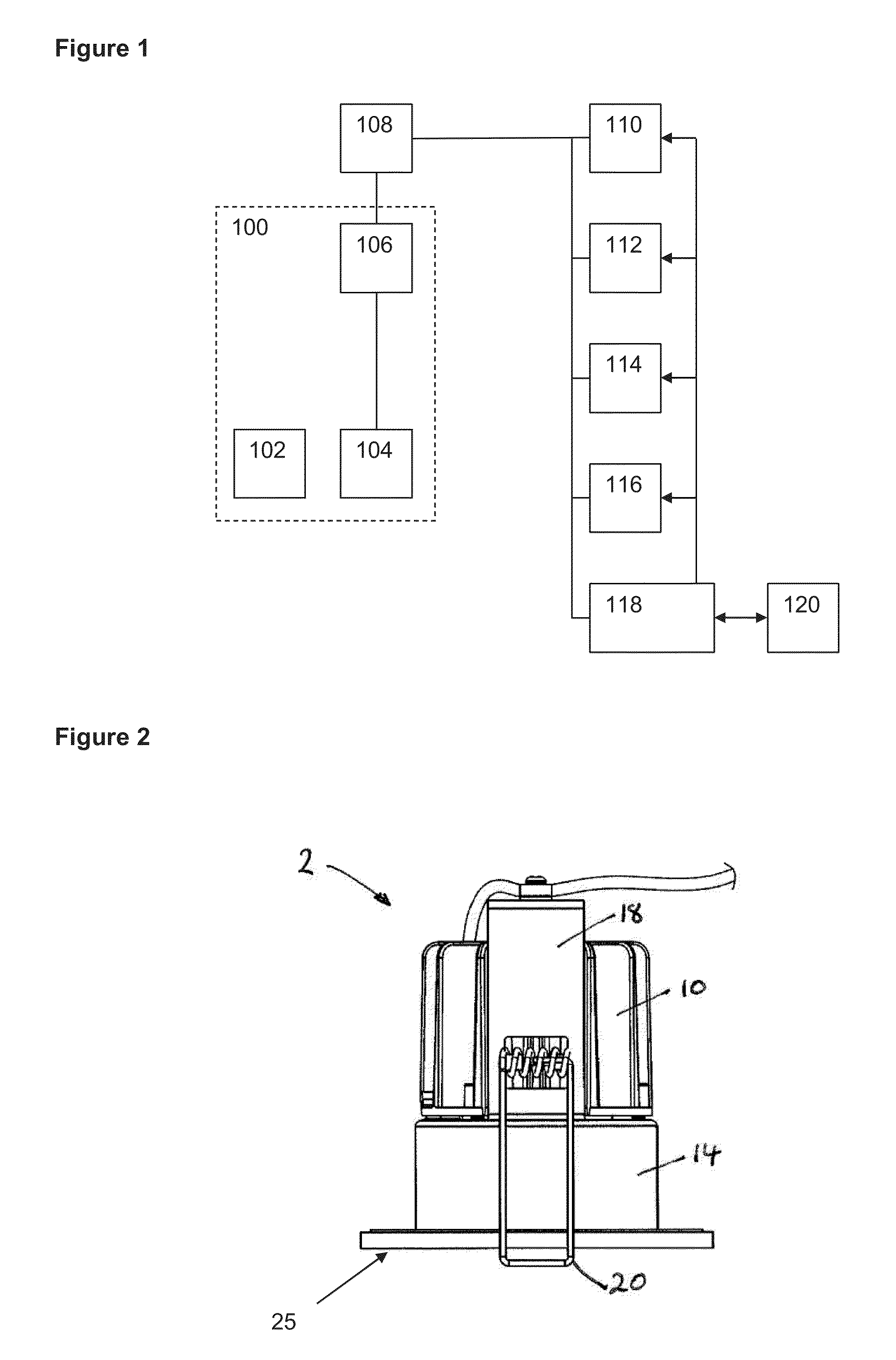
[0118]FIG. 1 shows a luminaire 100 of the present invention, comprising a fitting 102 for a lamp and a sensor 104. In FIG. 1, these are shown by the dashed lines to be contained within a housing of luminaire 100, but it is to be understood that sensor 104 may be located, at least partially, on the outside of the housing. Fitting 102 can hold any type of device used to emit light, such as an incandescent lamp, fluorescent lamp, light emitting diode, or LED light engine. The term luminaire is to be understood to encompasses similar terms such as light fixture and light fitting. The term lamp is to be understood to encompass similar terms such as light bulb, light or LED light engine. An LED light engine is a combination of one or more LED modules together with the associated electronic control gear or LED driver. An LED module contains one or more LEDs, together with further components, but excludes the control gear.

[0119]Sensor 104 includes devices able to sense information about the...


PUM


Abstract

A luminaire component for use in a luminaire, said component comprising:(i) an LED module on a first printed circuit board (PCB), the first PCB having a front face on which the LED module is located;(ii) a second PCB mounted forward of the front face of the first PCB;(iii) connection means adapted to connect the second PCB to the first PCB.The invention also extends to a luminaire bezel containing one or more sensors, where the bezel is removably attachable to the luminaire. The sensor(s) can measure one or more environmental characteristics and electrical and signal contacts between the bezel and the luminaire are provided. Preferably the electrical and signal contact means is cableless.

Description

CROSS-REFERENCE TO RELATED APPLICATIONS[0001]This application claims the benefit of U.K. Patent Application Nos. GB1409151.6 filed May 22, 2014; GB1415871.1 filed Sep. 8, 2014; GB1416540.1 filed Sep. 18, 2014; GB1422057.8 filed Dec. 11, 2014 and GB1502507.5 filed Feb. 13, 2015.BACKGROUND OF THE INVENTION[0002]The present invention is related to smart luminaires, and more specifically, approaches for incorporating sensors into various luminaire components and complete luminaires, and for communicating data from those sensors with local and distributed networks.[0003]Luminaires or light fixtures which include or are connected to a motion sensor are known, and these are particularly useful for causing a lamp in the luminaire to illuminate when a person is present. This is a convenient way of saving energy when an area is unoccupied, for eliminating light switches inside buildings, and for lighting pathways etc outside at night.[0004]A similar approach has also been developed for thermo...

Claims


Application Information

Patent Timeline
Patent Type & Authority Applications(United States)
IPC IPC(8): F21V23/04F21V5/04F21V23/06F21V23/00H05B44/00
CPCF21V23/0442F21V23/005F21Y2101/02F21V23/0435F21V23/06F21V5/048F21S2/00F21V17/10F21V23/00F21V23/04F21S8/026F21V23/045H05B45/00H05B47/19H05B47/115Y02B20/40F21V23/006F21V23/0471H05B47/105
Inventor JOHNSON, ANDREW
Owner GOOEE
Learn More