Hinge for doors of electrical household appliances

Inactive Publication Date: 2015-12-03
NUOVA STAR
View PDF25 Cites 19 Cited by
  • Summary
  • Abstract
  • Description
  • Claims
  • Application Information

AI Technical Summary

Benefits of technology

[0014]Another aim of this invention is to provide a hinge for doors of electrical household

Problems solved by technology

A drawback connected to the use of hinges of the type described above, using the weight force to determine the closing of the door and for this reason also defined as “gravity” type, is due to the fact that during the opening of the door, in order to accumulate the necessary potential energy, the door itself must rise, thus introducing instability to the system.
This latter type of hinge, altho

Method used


Image

  • Hinge for doors of electrical household appliances
  • Hinge for doors of electrical household appliances
  • Hinge for doors of electrical household appliances

Examples


Example

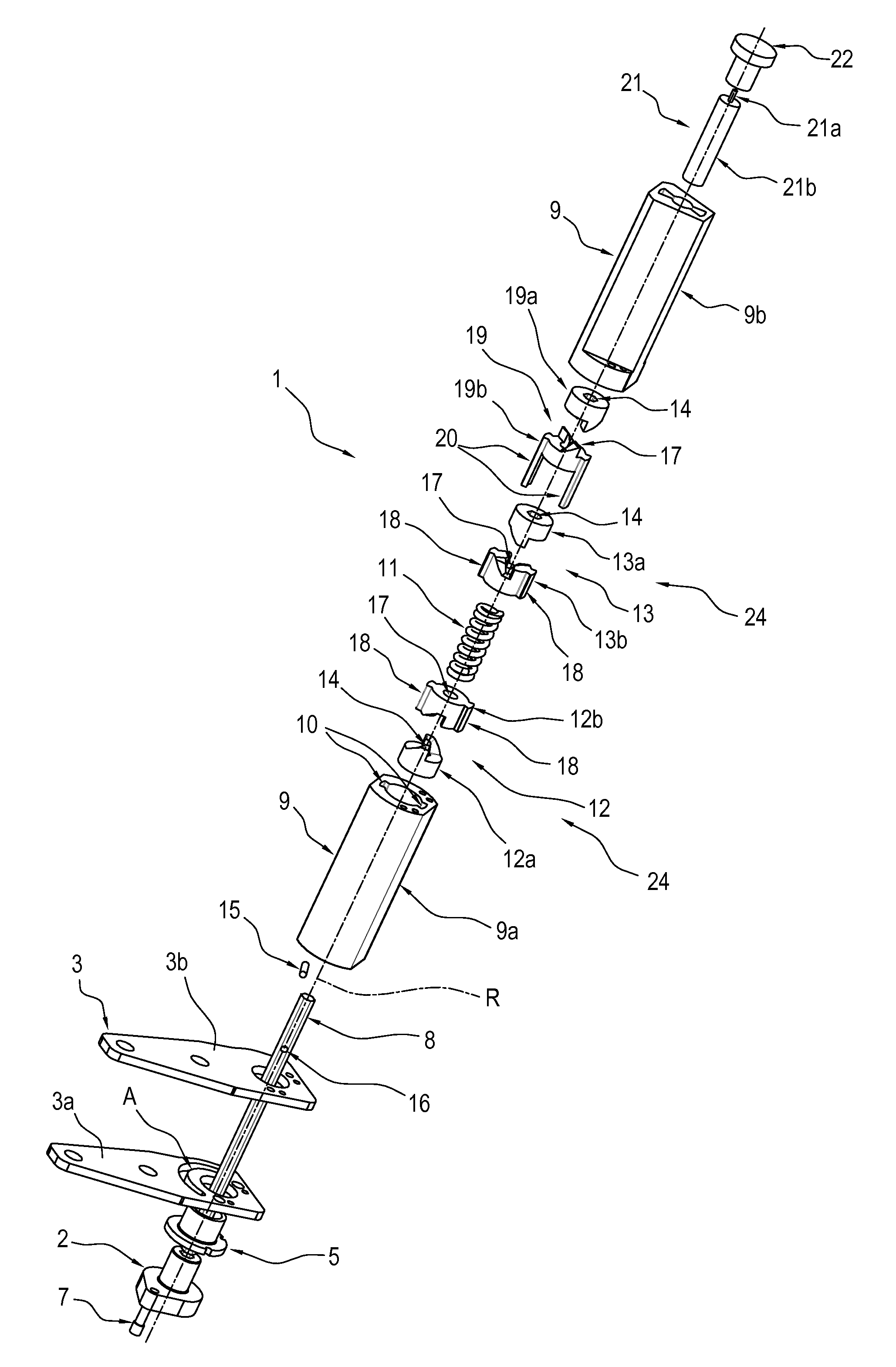
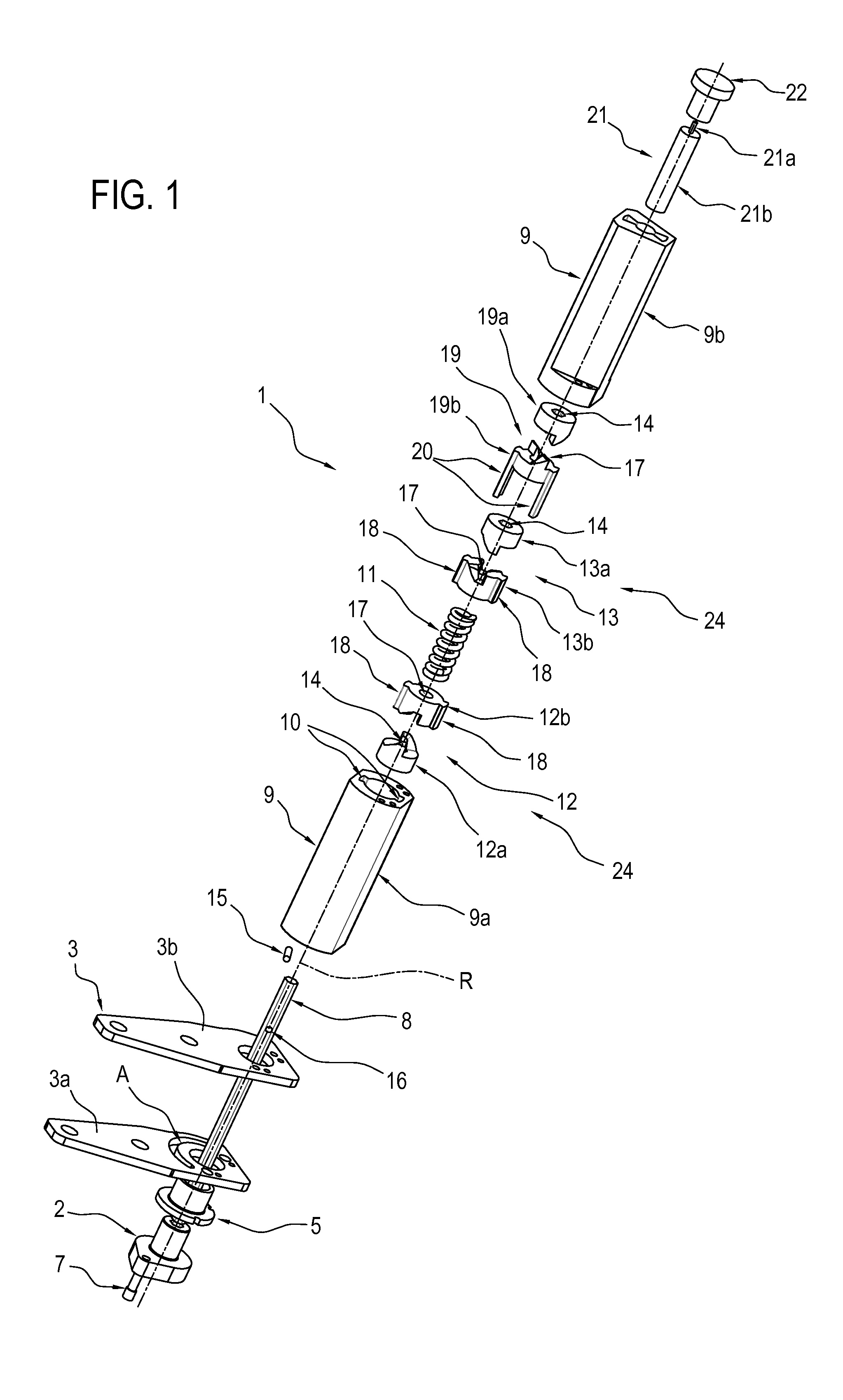
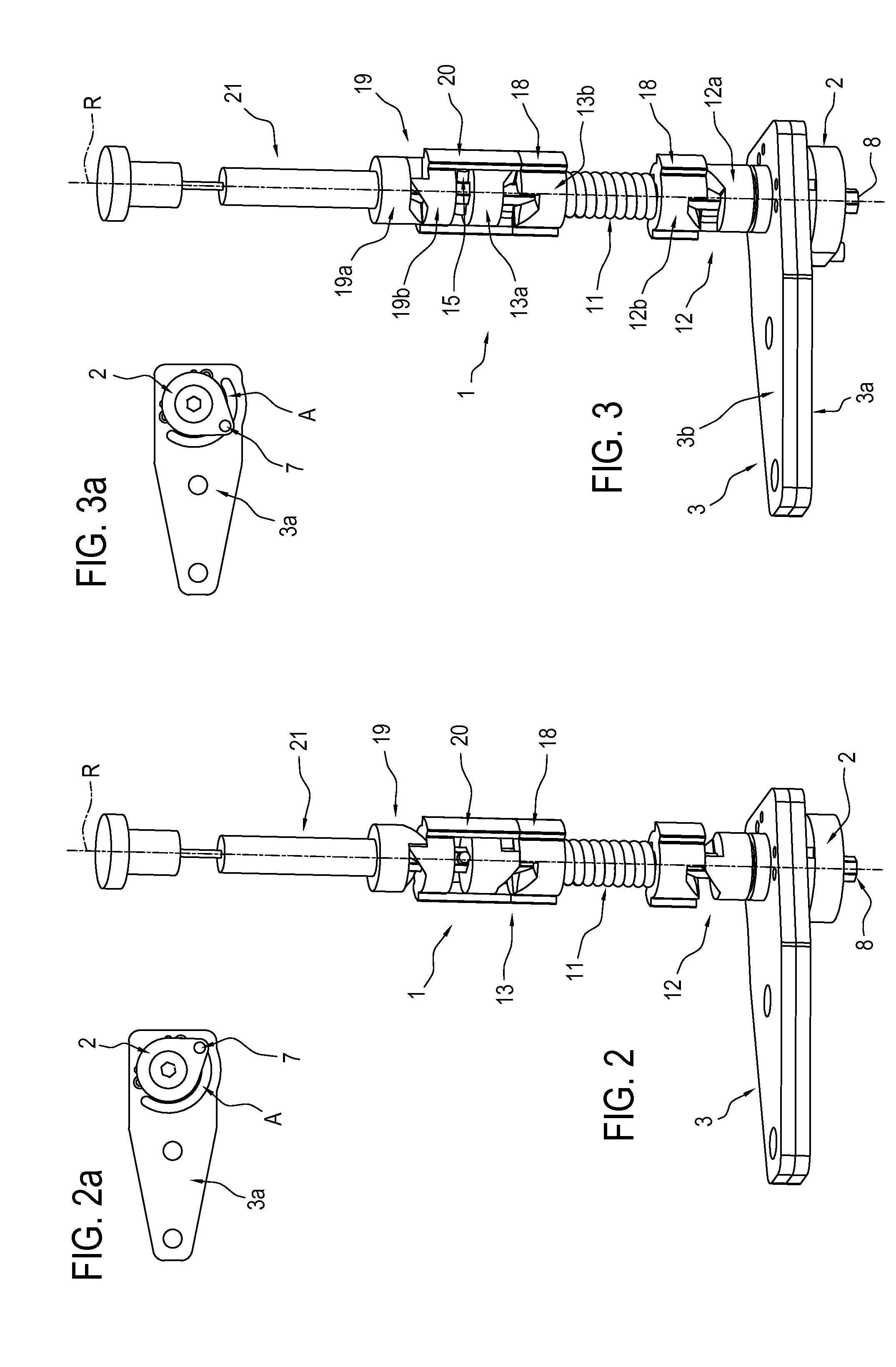
[0022]With reference to FIG. 1, the numeral 1 denotes in its entirety a hinge for doors of electrical household appliances made in accordance with this invention.

[0023]Preferably, but without limiting the invention, the term “electrical household appliance” used in this description refers to a refrigerator.

[0024]With reference to FIG. 1, the hinge 1 comprises a fixed body 2, connectable as one with to a frame, not illustrated, of the electrical household appliance, and a movable arm 3, connected to a door 4 of an electrical household appliance, shown in FIG. 6.

[0025]The hinge 1 is designed to make the door 4 movable relative to the above-mentioned frame, not illustrated, between a closed position and an open position.

[0026]The movable arm 3 is pivoted on the fixed body 2, by an interposed bush 5, to rotate relative to it about a respective axis R of rotation.

[0027]With reference to FIG. 6, the fixed body 2 is supported by a bracket 6 integral with the frame, not illustrated, of the ...


PUM


Abstract

A hinge for doors of appliances includes a movable arm connected to a door of the appliance, pivoted on a frame to rotate about an axis to make the door movable relative to the frame between closed and open positions. A control shaft extends longitudinally parallel to the axis and is connected to the frame. A sleeve attached to the movable arm extends parallel to the axis. An elastic element is contained inside the sleeve to generate an elastic force for closing the door. A mechanism drives the elastic element to determine the deformation and transmit to the movable arm the closing force. The mechanism includes two cylindrical cam operating units housed inside the sleeve, having first and second cylindrical cams operatively facing one another such that rotation of one about the axis determines translation of the other along the same axis and vice versa,

Description

[0001]This application claims priority to Italian Patent Application BO2014A000315 filed May 28, 2014, the entirety of which is incorporated by reference herein.BACKGROUND OF THE INVENTION[0002]This invention relates to a hinge for doors of electrical household appliances.[0003]More specifically, this invention relates to a hinge for doors of refrigerators.[0004]For connecting the doors of the refrigerators to the respective frame the prior art uses hinges with a vertical extension with cylindrical cams which, thanks to their inclined profile, allow a predetermined closing force to be transferred to the door.[0005]The closing force can be generated either by the weight of the door or by the action of a spring.[0006]The transformation of the weight force into twisting moment is caused by the inclination of the cylindrical cam profile. In effect, thanks to this inclination, the force which is transmitted between the inclined surfaces of the cams, in reality a cam and a follower, has a...

Claims


Application Information

Patent Timeline
IPC IPC(8): E05F3/20E05F3/14E05D3/02
CPCE05F3/20E05D3/02Y10T16/299Y10T16/2769Y10T16/283E05F3/14E05D11/06E05F1/1223E05F5/02E05F5/027E05Y2201/21E05Y2201/264E05Y2201/638E05Y2800/296E05Y2900/31
Inventor VANINI, MARCO
Owner NUOVA STAR
Why Eureka
Try Eureka