
Shaped Charge Casing Cutter

a cutter and shaped charge technology, applied in the direction of explosive charges, fluid removal, borehole/well accessories, etc., can solve the problems of large cutting volume, large volume of explosives, and large volume of explosives, and the formation of explosive torroids of sufficient size to sever a large diameter casing requires relatively large quantities of explosives, and the quantity of explosives exceeds prudent transportation limitations

Active Publication Date: 2015-12-03
W T BELL INT INC
View PDF0 Cites 15 Cited by
  • Summary
  • Abstract
  • Description
  • Claims
  • Application Information

AI Technical Summary

Benefits of technology

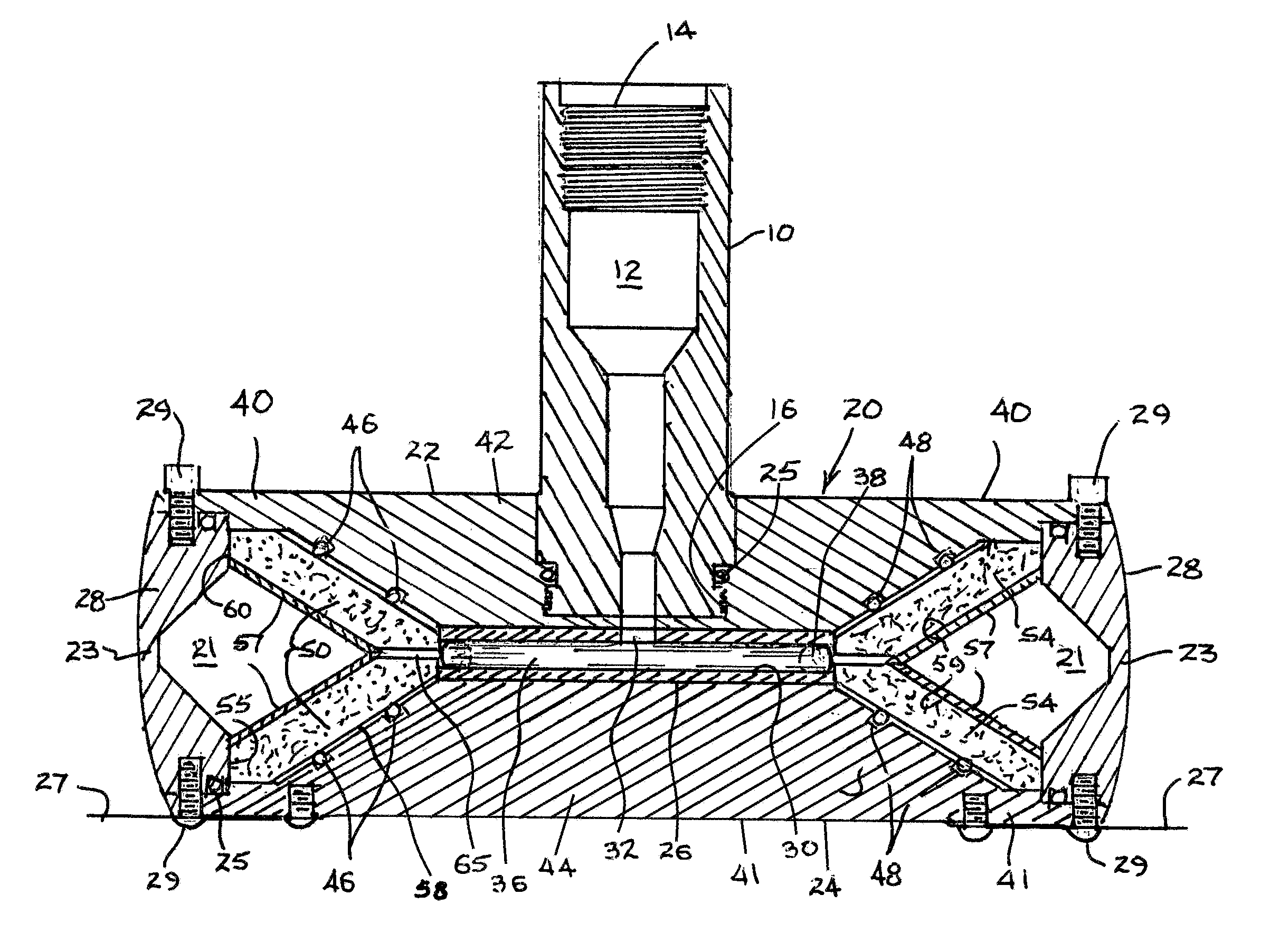
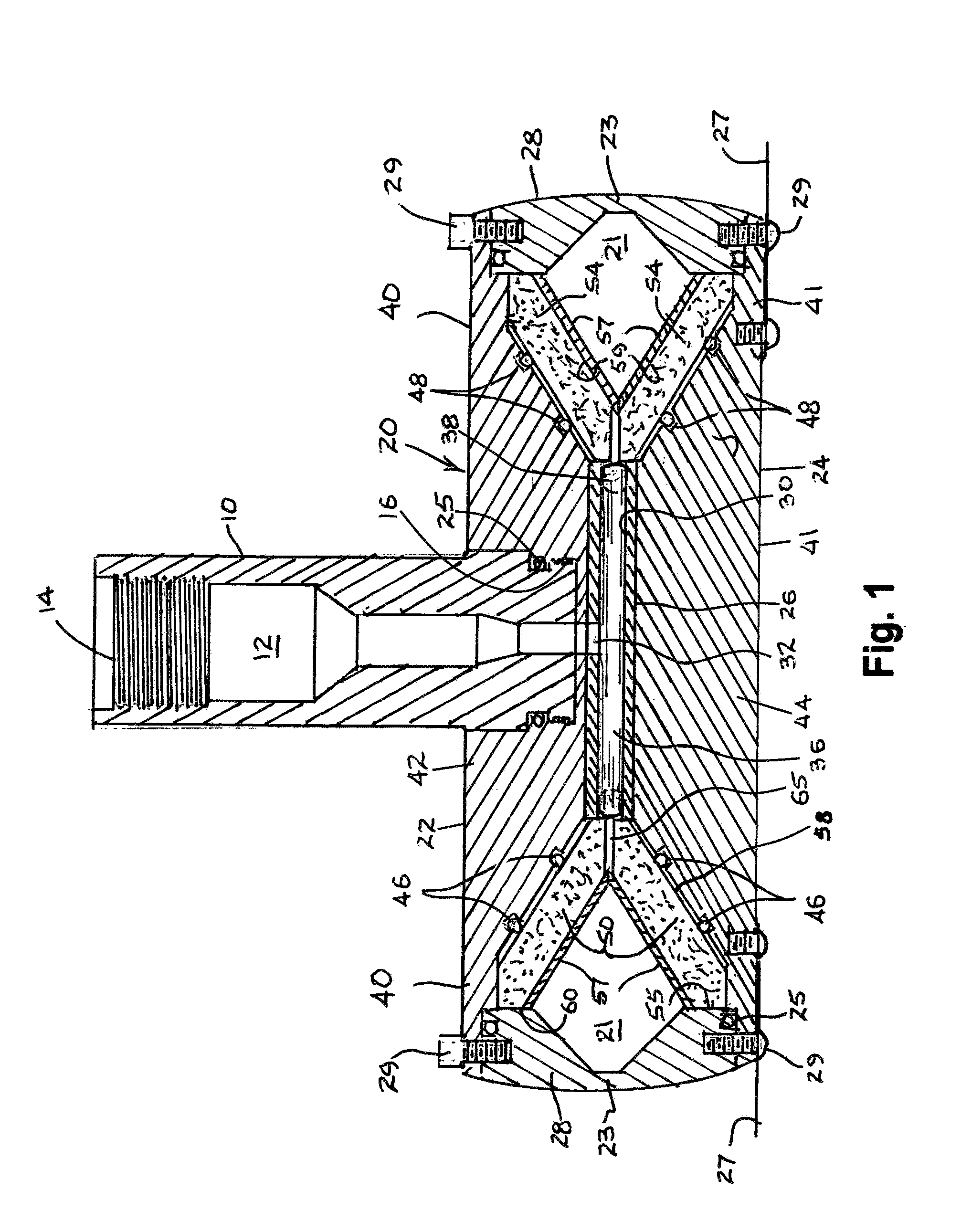
The casing cutter invention has several advantages including a solid interior that is resistant to high well pressure, a toroidal cavity filled with shaped charge explosive material, and a full-circle belting structure to hold the cavity open against well pressure. The shaped charge metal liner is divided into upper and lower halves, and the modules containing the explosive material are closed with shims to ensure a tight fit. The shaked charge assembly is biased against the liner cone surfaces to ensure a tight connection, and a gap between the module apex surfaces allows for tolerance variations during fabrication.

Problems solved by technology

Cutting large, 7 inch to 20 inch nominal diameter casing and casing liner is particularly challenging.
However, formation of an explosive torroid of sufficient size to sever a large diameter casing requires relatively large quantities of explosive.
As an integral unit, such quantities of explosive exceed prudent transportation limitations.
Unfortunately, the environmental circumstances of a drilling rig floor, which is where final cutter assembly must occur, are often severe and usually not conducive to the attentive care required for final assembly of a high explosive tool.
But large module assembly tolerance often results in collective space between modules.
In the case of modular assembly for shaped charges, such assembly space can severely diminish the cutter capability.
Other issues for large diameter casing cutters arise with deep wells under considerable hydrostatic pressure.
Large surface areas for prior art casing cutter housings may be distorted under deep well fluid pressure, also resulting in reduced cutting capacity or a malfunction of the tool.

Method used


Image

  • Shaped Charge Casing Cutter
  • Shaped Charge Casing Cutter
  • Shaped Charge Casing Cutter

Examples


Embodiment Construction

[0027]As used herein, the terms “up” and “down”, “upper” and “lower”, “upwardly” and downwardly”, “upstream” and “downstream”; “above” and “below”; and other like terms indicating relative positions above or below a given point or element are used in this description to more clearly describe some embodiments of the invention. However, when applied to equipment and methods for use in wells that are deviated or horizontal, such terms may refer to a left to right, right to left, or other relationship as appropriate. Moreover, in the specification and appended claims, the terms “pipe”, “tube”, “tubular”, “casing”, “liner” and / or “other tubular goods” are to be interpreted and defined generically to mean any and all of such elements without limitation of industry usage.

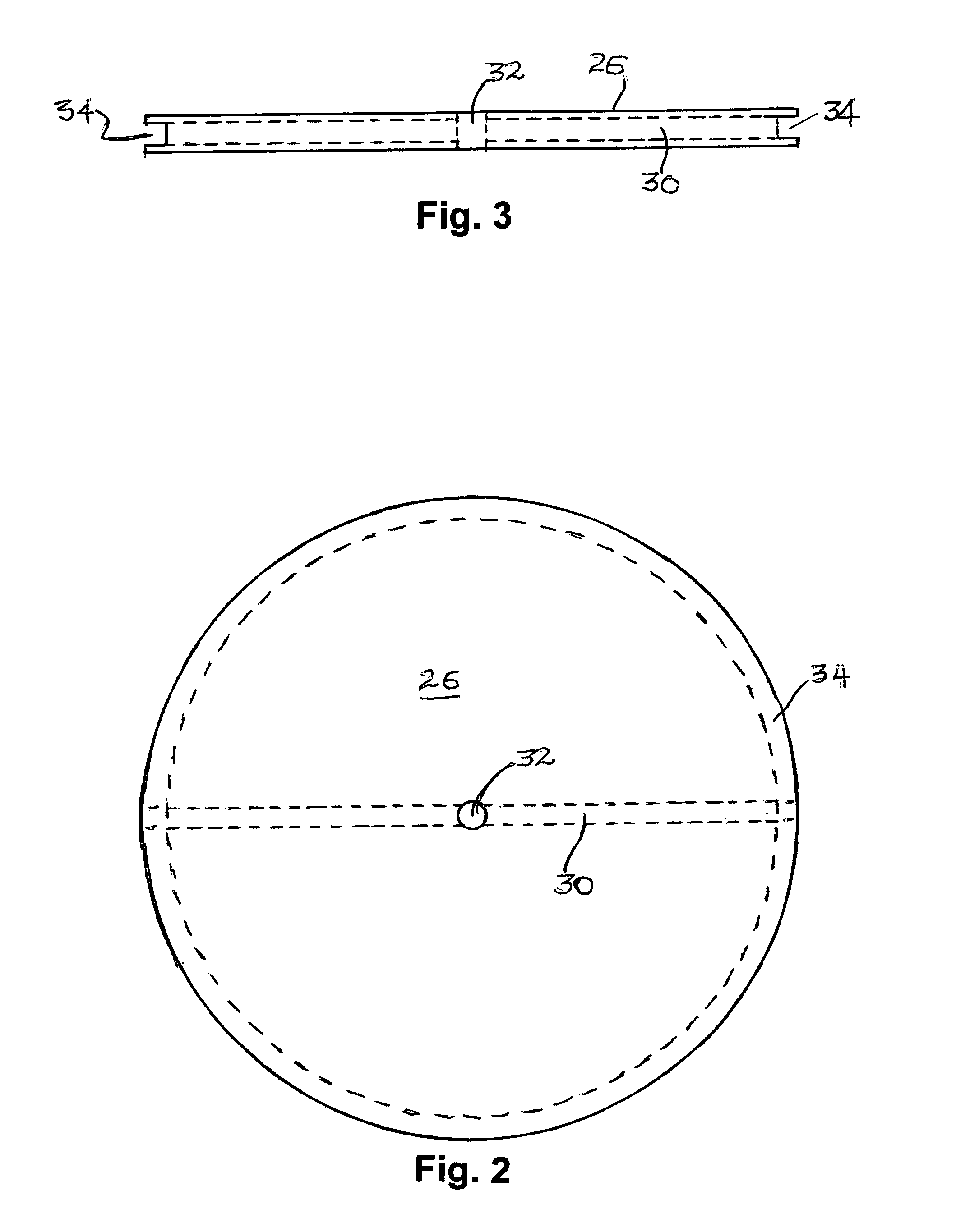
[0028]Referring to FIG. 1, a top sub 10 is formed with an axial cavity 12 for receipt of a detonator sub-assembly not shown. Internal threads 14 proximate of the sub body upper end provide a convenient mechanism for securi...


PUM


Abstract

A shaped charge casing cutter is constructed with the cutter explosive formed into radial section modules aligned in a toroidal cavity between a pair of housing plates. The center sections of the housing plates are contiguously aligned with opposite parallel surfaces of a center disc. The housing plates comprise annular edges or rims, and the rims can be offset from respective center disc planes in opposite directions from each other to form a toroidal cavity. The toroidal cavity is enclosed by a circumferential belt secured to said housing plate rims. V-grooved shaped charge explosive in the form of multiple pi sections is distributed about the cavity to intimately contact a pair of frusto-conical liners. Assembly tolerance space between the pi sections is filled by dense paper card stock.

Description

CROSS-REFERENCE TO RELATED APPLICATIONS[0001]This application is a continuation-in-part of and claims priority to pending U.S. patent application Ser. No. 14 / 120,528, entitled “Shaped Charge Casing Cutter,” filed May 29, 2014.STATEMENT REGARDING FEDERALLY SPONSORED RESEARCH OR DEVELOPMENT[0002]Not ApplicableFIELD OF THE INVENTION[0003]The present invention relates to shaped charge tools for explosively severing tubular goods including, but not limited to, pipe, tube, casing and / or casing liner.BACKGROUND OF THE INVENTION[0004]The capacity to quickly, reliably and cleanly sever a pipe or well casing deeply within a wellbore is an essential maintenance and salvage operation in the petroleum drilling and exploration industry. Cutting large, 7 inch to 20 inch nominal diameter casing and casing liner is particularly challenging. Generally, the industry relies upon mechanical, chemical or pyrotechnic devices for such cutting. Among the available options, shaped charge (SC) explosive cutte...

Claims


Application Information

Patent Timeline
IPC IPC(8): E21B29/02F42B1/02
CPCF42B1/02E21B29/02E21B43/117F42B1/028F42B3/006
Inventor BELL, WILLIAM T.RAIRIGH, JAMES G.
Owner W T BELL INT INC
Learn More