Driving method of liquid display panel

a technology of liquid display panel and driving method, which is applied in the direction of electric digital data processing, instruments, computing, etc., can solve the problems of very short pixel charging time in the hsd structure, increased power consumption of data lines on one hand, and excessive signal frequency, so as to reduce power consumption of hsd structure panel and efficiently improve the charging conditions of pixels. , the effect of reducing the frequency of the positive/negative polarity switching of signals on data lines

Inactive Publication Date: 2015-12-03
SHENZHEN CHINA STAR OPTOELECTRONICS TECH CO LTD
View PDF5 Cites 1 Cited by
  • Summary
  • Abstract
  • Description
  • Claims
  • Application Information

AI Technical Summary

Benefits of technology

[0011]An objective of the present invention is to provide a driving method of a liquid display panel. On the basis of achieving dot inversion, the frequency of the positive / negative polarity switching of the signals on the data lines is enormously reduced. Accordingly, the power consumption of HSD structure panel is reduced. The charging conditions of the pixels are efficiently improved and the display quality is enhanced.

Problems solved by technology

Here come the drawbacks, the signal frequency is too high and the power consumption of the data lines is increased on one hand.
On the other hand, the pixel charging time in the HSD structure is very short, and the RC delay effect of the signal switching on the data lines may further influence the pixel charging condition.
When the resolution of the liquid crystal display is raised, such issues become serious even more.

Method used


Image

  • Driving method of liquid display panel
  • Driving method of liquid display panel
  • Driving method of liquid display panel

Examples


first embodiment

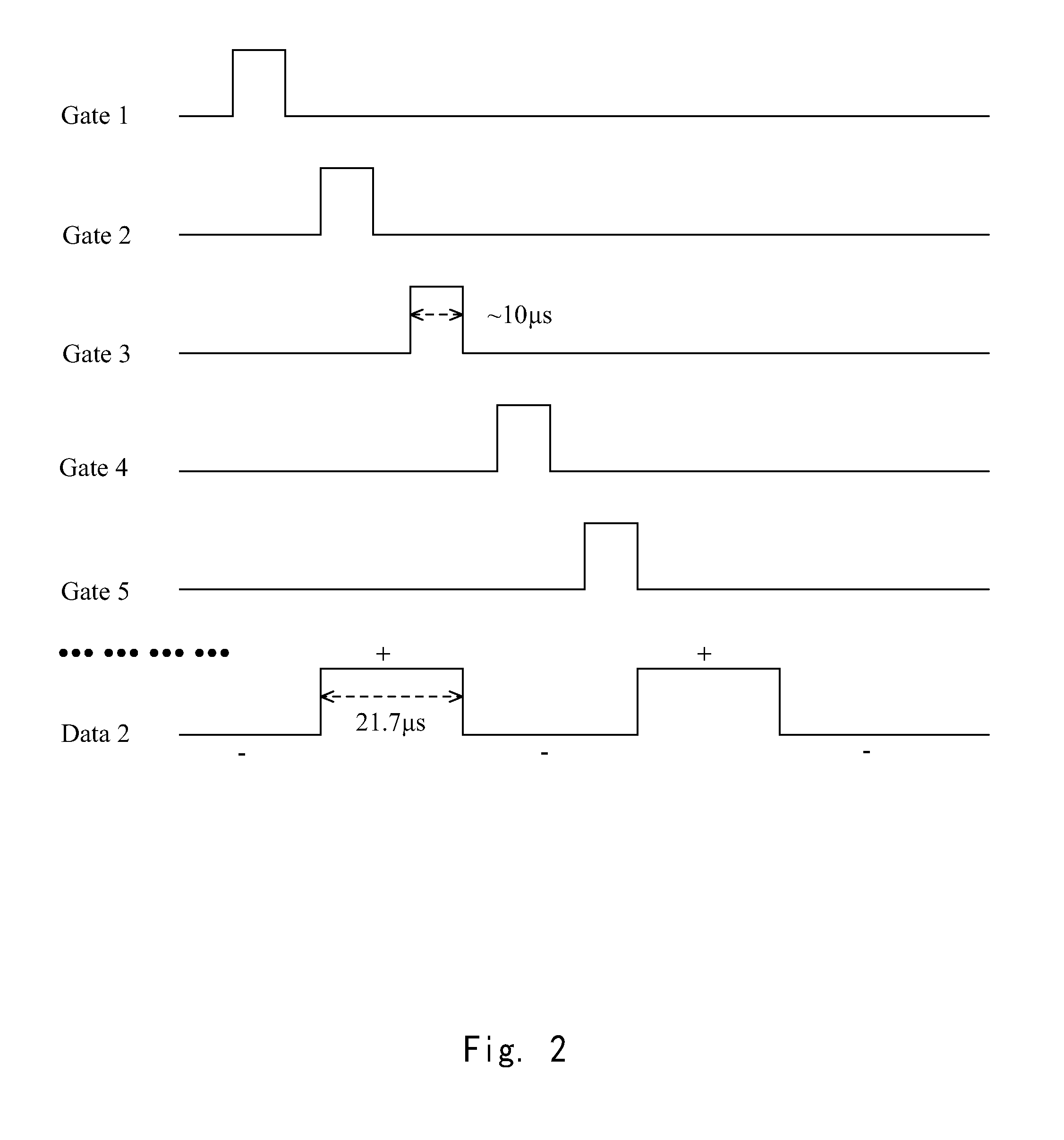
[0056]Please refer to FIG. 4 in conjunction with FIG. 1 and FIG. 3. FIG. 4 is a sequence diagram of employing the driving method of the present invention in FIG. 1. In scenario that m is 1536, and the first polarity is negative polarity (−) and the second polarity is positive polarity (+). Specifically, the second data line (Data2) shown in FIG. 1 (the resolution of the liquid crystal panel is HD, the resolution is 1366×768 and the working frequency is 60 Hz) is illustrated. The gate lines are conducted according to a sequence of 1→4→5→ . . . 4n→4n+1→ . . . →1533→1536→2→3→ . . . 4n+2→4n+3→ . . . →1534→153 5 to complete the signal writing of a whole frame. The driving voltages of the corresponding data signals are negative polarity (−) during the period when the 1th gate line to the 1536th gate line (Gate1→Gate1536) are conducted, and the driving voltages of the corresponding data signals are positive polarity (+) during the period when the 2th gate line to the 1535th gate line (Gate...

second embodiment

[0057]Please refer to FIG. 5 in conjunction with FIG. 1 and FIG. 3. FIG. 5 is a sequence diagram of employing the driving method of the present invention in FIG. 1. Likewise, in scenario that m is 1536, and the first polarity is negative polarity (−) and the second polarity is positive polarity (+). Specifically, the second data line (Data2) shown in FIG. 1 (the resolution of the liquid crystal panel is HD, the resolution is 1366×768 and the working frequency is 60 Hz) is illustrated. The gate lines are conducted according to a sequence of 1→4→5→ . . . 4n→4n+1→ . . . →1533→1536→1535→1534→ . . . 4n+3→4n+2→ . . . →3→2 to complete the signal writing of a whole frame. The driving voltages of the corresponding data signals are negative polarity (−) during the period when the 1th gate line to the 1536th gate line (Gate1→Gate1536) are conducted, and the driving voltages of the corresponding data signals are positive polarity (+) during the period when the 1535th gate line to the 2th gate l...


PUM


Abstract

The present invention provides a driving method of a liquid display panel, comprising: providing a plurality of data lines, a plurality of gate lines (Gate 1-Gate m), and a plurality of pixels (P), and each of the pixels is connected with one data line and one gate line, and the polarity of each of the pixels are opposite to the polarities of adjacent pixels at up, down, left and right; sequentially conducting the gate lines of the pixels which are first polarity corresponding to a driving voltage to complete signal writing of a half frame; sequentially conducting the gate lines of the pixels which are second polarity corresponding to a driving voltage to complete signal writing of the other half frame; the first polarity is opposite to the second polarity, and the m is a multiple of 4. By using the driving method of the liquid display panel, the signal of the data line merely switches the polarity of the driving voltage twice in a period of a frame. The power consumption of the whole panel is reduced. The charging conditions of the pixels are improved and the display quality is enhanced.

Description

FIELD OF THE INVENTION[0001]The present invention relates to the field of liquid crystal display, and more particularly to a driving method of a liquid display panel.BACKGROUND OF THE INVENTION[0002]TFT-LCD (Thin Film Transistor Liquid Crystal Display) possesses properties of small occupied space, low power consumption and no radiation. It dominates the major part of the current flat display panel's market. A TFT-LCD mainly comprises an array substrate and a color film substrate, which are cell assembled to sandwich the liquid crystals therebetween. Gate lines for supplying scan signals, data lines for supplying data signals, pixel electrodes and thin film transistors of forming pixels are formed on the array substrate. Each pixel electrode is controlled by the thin film transistor. When the thin film transistor is conducted, the pixel electrode is charged during the period of conducting time. After the thin film transistor is off, the voltage of the pixel electrode is maintained un...

Claims


Application Information

Patent Timeline
Patent Type & Authority Applications(United States)
IPC IPC(8): G09G3/36
CPCG09G3/3648G09G3/3688G09G2320/043G09G3/3696G09G2330/021G09G3/3614
Inventor DU, PENG
Owner SHENZHEN CHINA STAR OPTOELECTRONICS TECH CO LTD
Why Eureka
Try Eureka