Inductive charging device

a charging device and inductive technology, applied in the direction of manufacturing tools, transportation and packaging, portable power-driven tools, etc., can solve the problems of additional bearing forces, special force and torques required for the suspension support, and the installation effort of the fastening frame may be particularly low

Active Publication Date: 2015-12-03
ROBERT BOSCH GMBH
View PDF4 Cites 14 Cited by
  • Summary
  • Abstract
  • Description
  • Claims
  • Application Information

AI Technical Summary

Benefits of technology

[0050]The spring elements together with the fastening frame particularly advantageously have a one-piece design. In particular, the spring elements together with the bearing lugs may be connected as one piece to the fastening frame. The fastening frame may preferably be formed, at least partially, from a plastic component, in particular a plastic component manufactured in an injection molding process. The fastening frame may be particularly inexpensive and / or robust. The installation effort for the fastening frame may be particularly low. The situation may be avoided that spring elements and / or bearing lugs come loose from the fastening frame.
[0051]In addition, it is provided that at least two bearing lugs, viewed along the insertion direction, are situated in succession. Secure fastening may advantageously be made possible in this way.

Problems solved by technology

Forces and in particular torques which are required for a suspended support may be particularly small.
A fastening means for supporting the system may be exposed to particularly small forces and torques.
In particular, the inductive charging unit may include an electrical battery interface which in addition to electrical contacting of the inductive charging unit results in additional bearing forces.
The installation effort for the fastening frame may be particularly low.

Method used


Image

  • Inductive charging device
  • Inductive charging device
  • Inductive charging device

Examples


Embodiment Construction

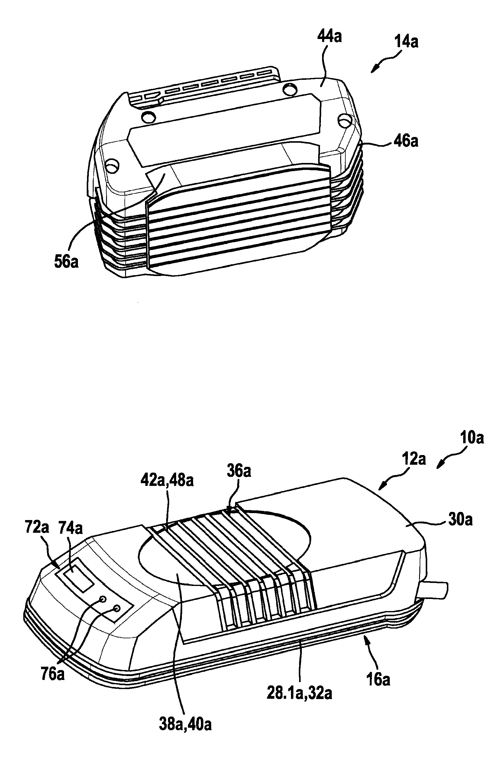
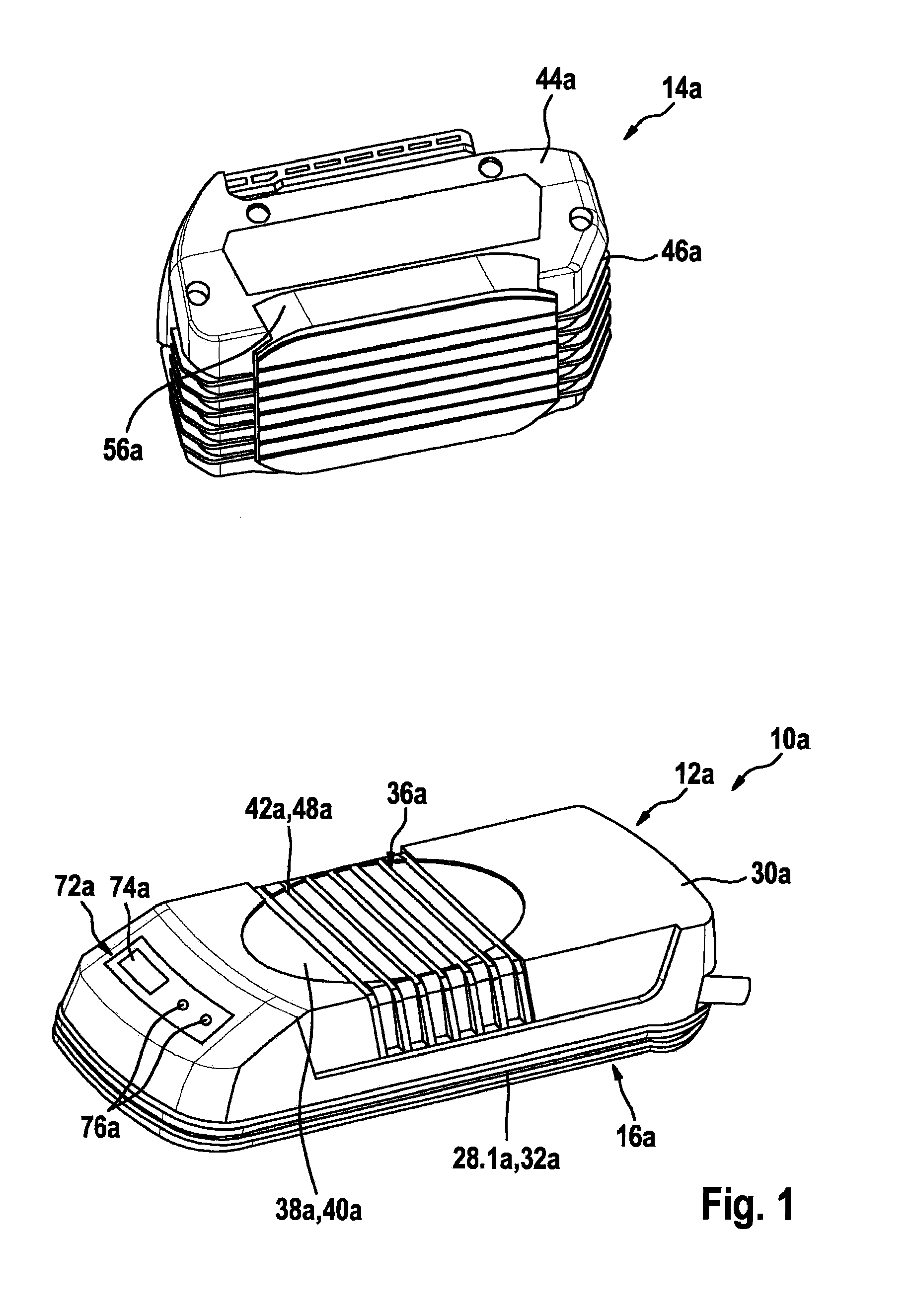
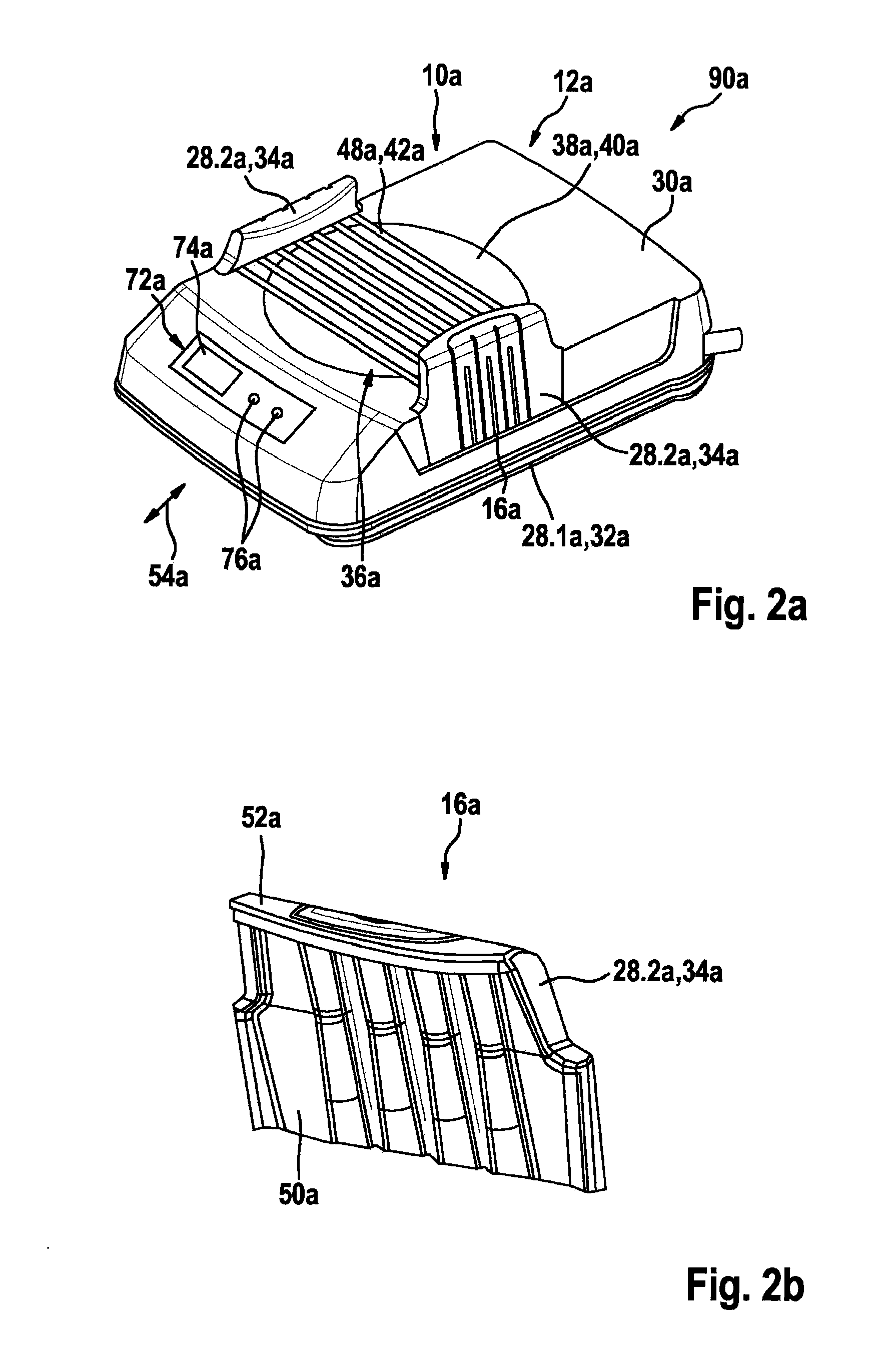
[0082]FIG. 1 illustrates a system 90g which includes an inductive charging unit 12a and an induction battery 14a. Inductive charging unit 12a is provided for electrically charging induction battery 14a in a state of charge. Induction battery 14a is designed as a hand-held power tool induction battery. Induction battery 14a has a design which is inductively chargeable with the aid of inductive charging unit 12a. Induction battery 14a is designed to be coupleable to inductive charging unit 12a. Inductive charging unit 12a is provided for transmitting energy to induction battery 14a in a coupled state with induction battery 14a. Inductive charging unit 12a is designed as a hand-held power tool inductive charging unit. Inductive charging unit 12a is designed as an inductive charging device. Inductive charging unit 12a includes a charging coil, not illustrated, and a housing 30a. Housing 30a encloses the charging coil. The charging coil is provided for inductively transmitting energy to ...


PUM


Abstract

An inductive charging device is provided, in particular a hand-held power tool inductive charging device, which includes an inductive charging unit which is provided for transferring energy in a coupled state with an induction battery. It is provided that the inductive charging device includes a fastening unit which is provided, at least in part, for coupling the inductive charging unit to the at least one induction battery and/or to at least one external unit in at least one state.

Description

BACKGROUND INFORMATION[0001]An inductive charging device has previously been provided.SUMMARY[0002]The present invention is directed to an inductive charging device, in particular a hand-held power tool inductive charging device, which includes an inductive charging unit which is provided for transferring energy in a coupled state with an induction battery.[0003]It is provided that the inductive charging device includes a fastening unit which is provided, at least in part, for coupling the inductive charging unit to the at least one induction battery and / or to at least one external unit in at least one state.[0004]In the present context, an “inductive charging unit” is understood in particular to mean a unit for charging the at least one induction battery, and which is provided for relaying a charging current, at least partially by electromagnetic induction, to the induction battery in at least one state of charge, and which includes at least one inductive charging coil. In the pres...

Claims


Application Information

Patent Timeline
Patent Type & Authority Applications(United States)
IPC IPC(8): H02J7/02H02J7/00
CPCH02J7/0044H02J7/025B25F5/00B25H3/00H02J7/0045H02J7/0042H02J50/10H02J50/90
Inventor BREITENBACH, JANKRUPEZEVIC, DRAGANMACK, JUERGENLOHR, GUENTERREJMAN, MARCIN
Owner ROBERT BOSCH GMBH
Why Eureka
Try Eureka