
Load-absorbent device for introducing load forces such as cable forces or tensioning forces of sheet-like structures

Inactive Publication Date: 2014-06-24
CARL STAHL GMBH & CO KG
View PDF12 Cites 9 Cited by
  • Summary
  • Abstract
  • Description
  • Claims
  • Application Information

AI Technical Summary

Benefits of technology

The invention provides an improved load-absorbing device with a simple design that reduces installation effort. The device has a connecting device with a wing that makes it easier to connect tensioning members to a tension rod. This design also allows for easier mounting of tensioning structures on edge regions with no securing points. The tension rod has an adjusting nut that facilitates tensioning or retensioning of the connecting device and tensioning members. Overall, the invention simplifies the process of installing and maintaining a load-absorbing device.

Problems solved by technology

This arrangement leads to considerable installation effort, especially since pertinent bearing elements may not be comfortably accessible on the support system of the supporting structure, such as, for example, supports, with varying inclination.

Method used


Image

  • Load-absorbent device for introducing load forces such as cable forces or tensioning forces of sheet-like structures
  • Load-absorbent device for introducing load forces such as cable forces or tensioning forces of sheet-like structures
  • Load-absorbent device for introducing load forces such as cable forces or tensioning forces of sheet-like structures

Examples


Embodiment Construction

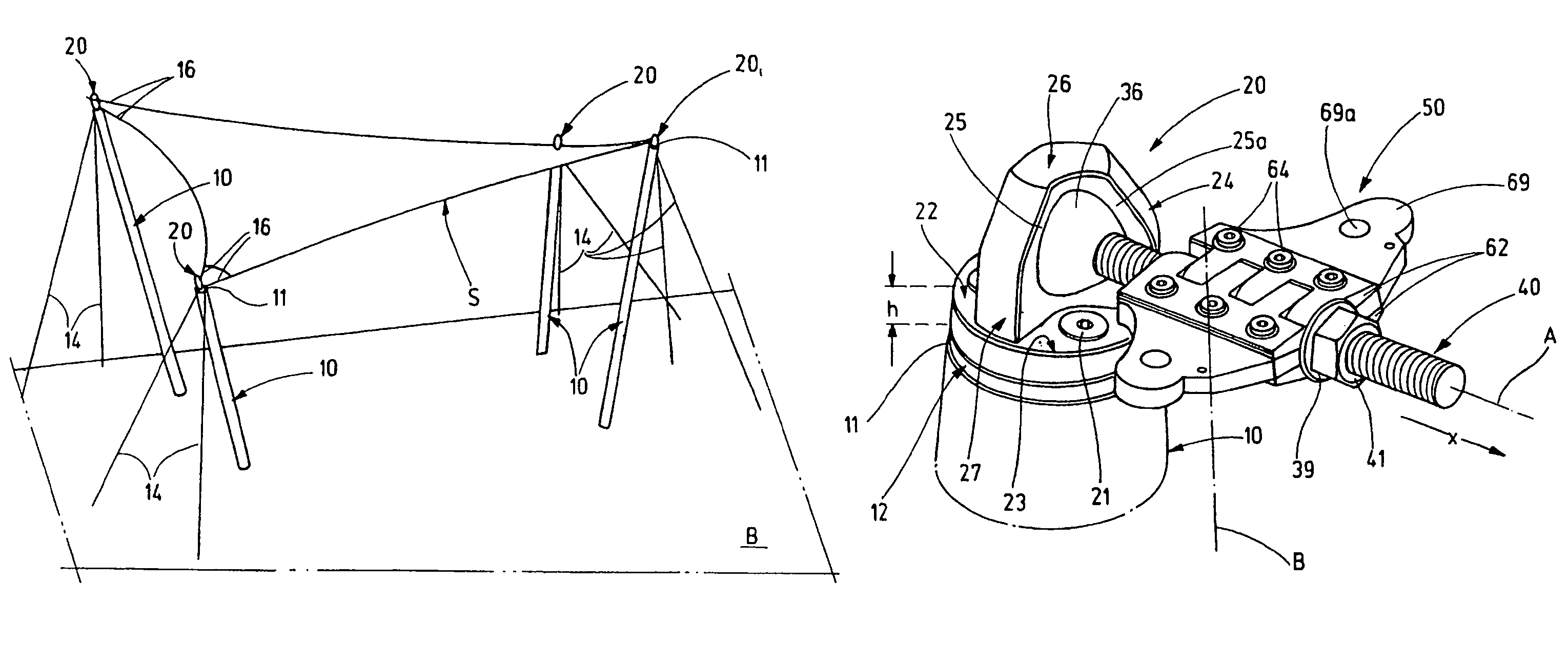
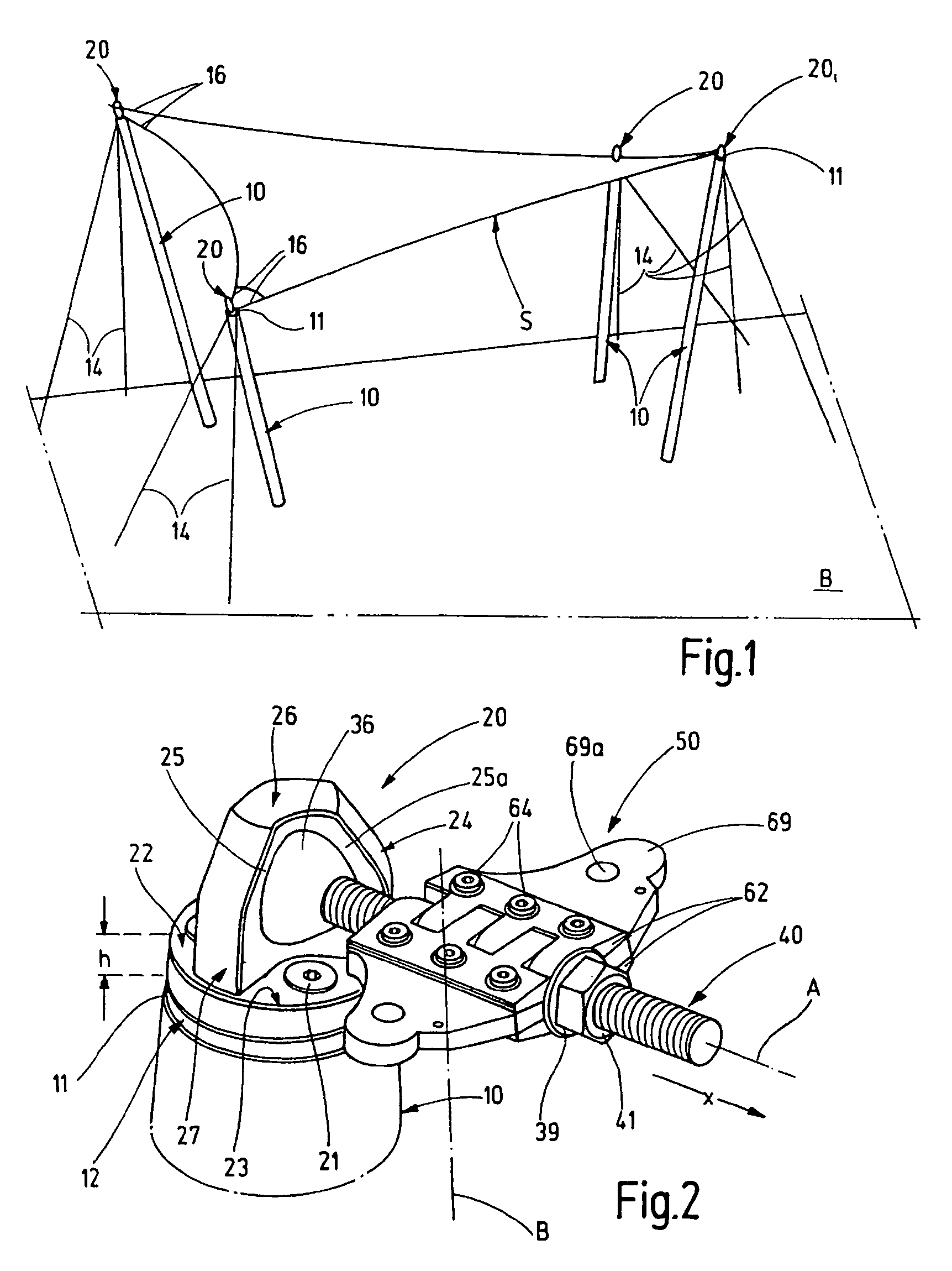
[0072]A plane load-bearing structure has, according to FIG. 1, four somewhat outwardly inclined columns 10. Columns 10 are set apart from each other and reach upward in pairs from a floor area B and stretch between their free ends 11 a sail or membrane S having an approximately rectangular contour and made of a textile material to serve as a membrane-like roof surface. The membrane free ends 11 are tensioned by cables 14 against the floor area B and anchors (not illustrated herein) that are secured on the floor. The four corner regions of this membrane S or a correspondingly constructed net are connected in each case by short cable strands 16 to hinge joints 20 projecting from the head surface 12k of the column 10. The head surface 12k forms the upper edge of the supporting structure and is formed by an end disk 12 inserted into the column 10.

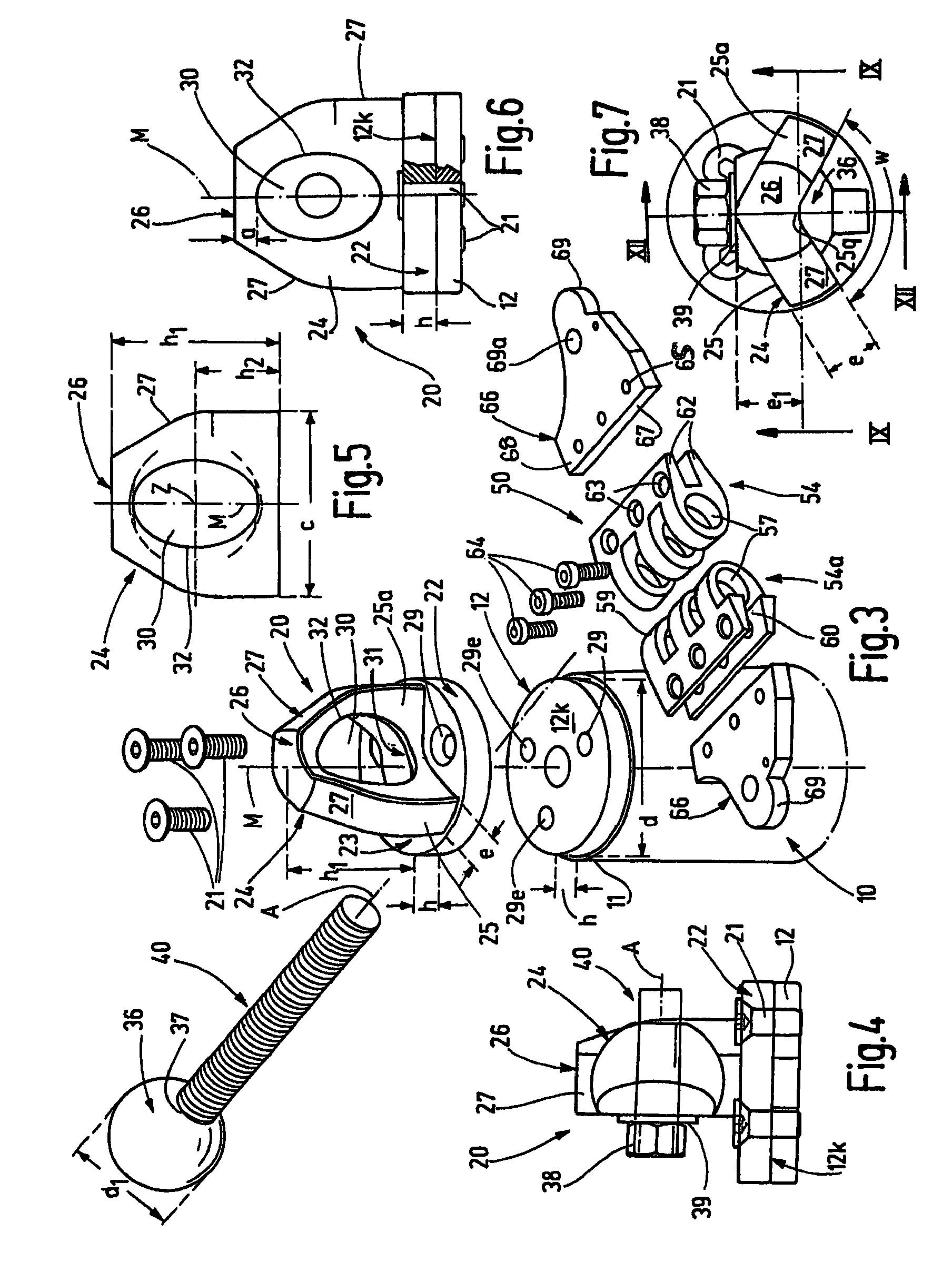
[0073]According to FIGS. 2 and 3, a base plate 22 having a diameter d of, for example, 117 mm and a height h of, for example, 20 mm, of the hi...


PUM


Abstract

A load-absorbing device initiates load forces such as cable forces or tensioning forces of sheet-shaped structures into supporting structures (10). At least one bearing element (24, 80) is anchored on supporting structure (10). A tie rod (40) of a load-absorbing part (36, 40) is connected to the bearing element. A connection device (50) for tension members (16; 98) cooperates with the tie bar (40). The connection device (50) has at least one connection wing (66) projecting laterally from the longitudinal axis (A) and forming at least one connection point (69a) offset with respect to the longitudinal axis (A).

Description

FIELD OF THE INVENTION[0001]The invention relates to a load-absorbent device for introducing load forces, such as cable forces or tensioning forces of sheet-like structures, into supporting structures. The device comprises at least one bearing element anchored to the pertinent supporting structure, a tension rod of a load-absorbent part connected to the bearing element, and a connecting device for tensioning members interacting with the tension rod.BACKGROUND OF THE INVENTION[0002]Modern architecture has increasingly incorporated concepts of load-bearing structures, where planar elements, such as tent-like or umbrella-like coverings that form, as a textile building material, part of a load-bearing structure. Such structures are anchored or erected on support systems, for example, steel supports. To form the respective elements form space-creating structures of a desired architectural design, the respective suitable introduction of load forces, in particular, the tensioning or bearin...

Claims


Application Information

Patent Timeline
IPC IPC(8): E04H15/32E04H15/58
CPCF16C11/0623E04H15/58Y10T403/32Y10T403/32631
Inventor KIEFER, MICHAEL
Owner CARL STAHL GMBH & CO KG
Learn More