Clamp apparatus

Active Publication Date: 2015-12-10
SMC CORP
View PDF5 Cites 2 Cited by
  • Summary
  • Abstract
  • Description
  • Claims
  • Application Information

AI Technical Summary

Benefits of technology

[0014]Accordingly, even if the driving force output from the drive unit is small, by boosting the driving force with the transmission levers, the workpiece can

Problems solved by technology

However, with the aforementioned clamp apparatus, from an initial condition in which clamping of a workpiece is started by the clamp arms to a clamped condition in which the workpie

Method used


Image

  • Clamp apparatus
  • Clamp apparatus
  • Clamp apparatus

Examples


Embodiment Construction

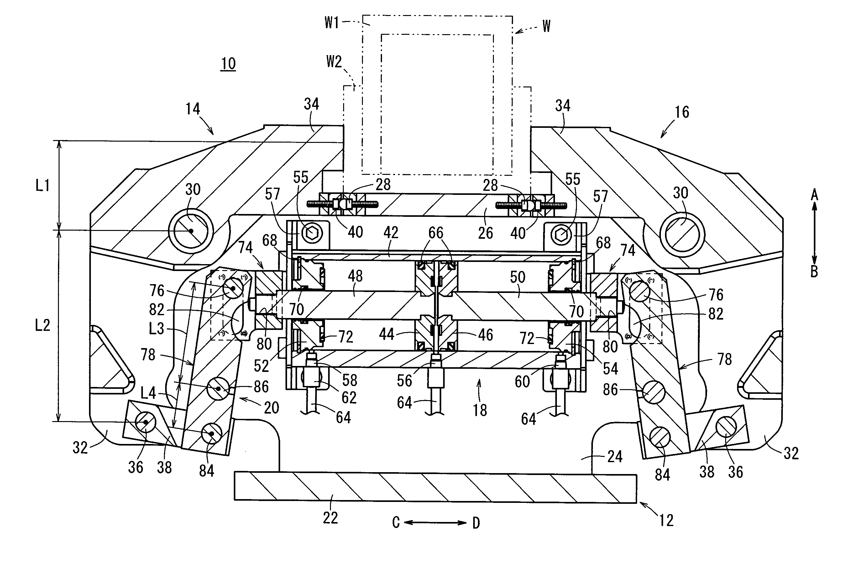
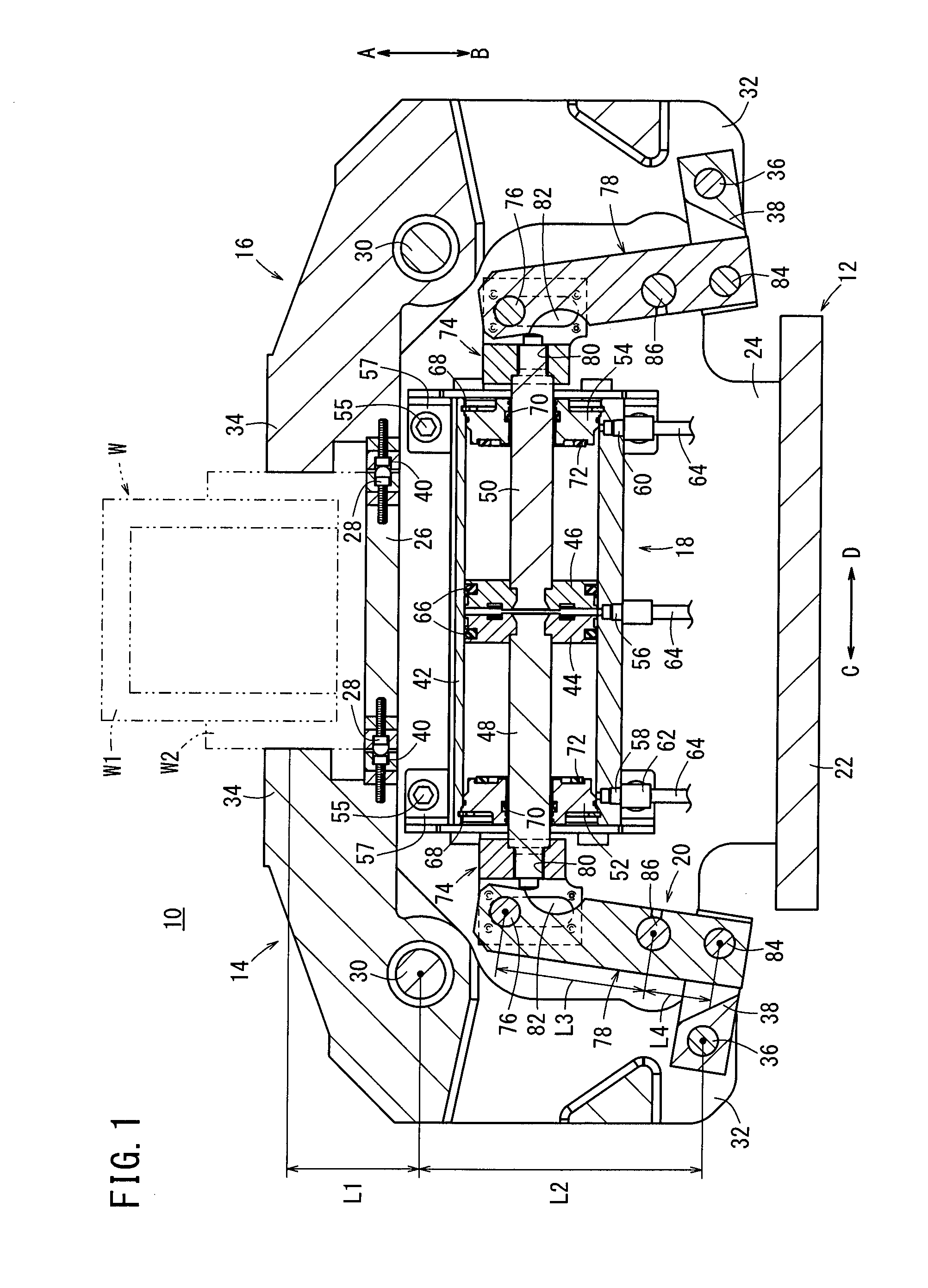
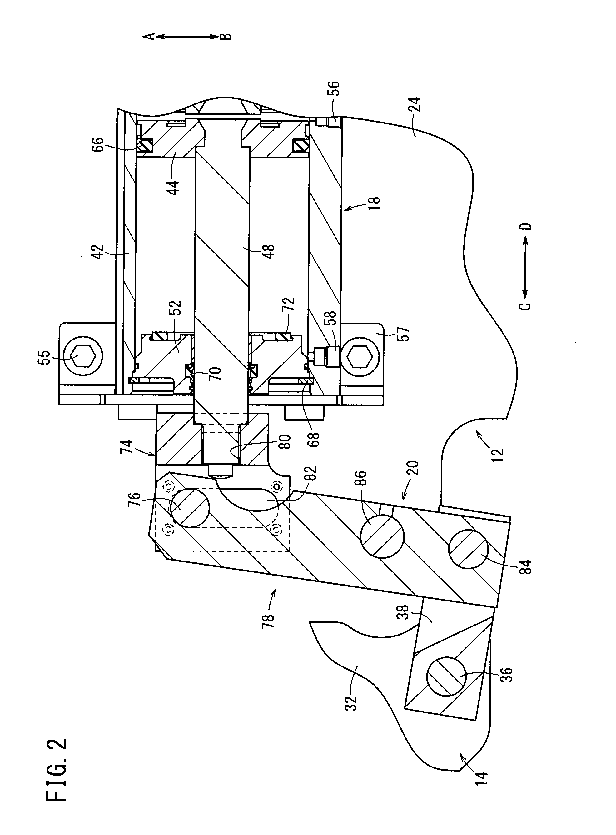
[0021]As shown in FIGS. 1 through 3, a clamp apparatus 10 includes a body 12, a pair of first and second clamp arms 14, 16, which are pivotally supported rotatably with respect to the body 12, a drive unit 18 fixed to the body 12, and a driving force transmission mechanism 20 that transmits a driving force of the drive unit 18 to the first and second clamp arms 14, 16.

[0022]The body 12 is constituted from a plate-shaped base 22, which is arranged horizontally, and a pair of plate members 24, which are separated mutually by a predetermined distance, and are connected respectively to opposite side surfaces of the base 22. The plate members 24 are disposed perpendicularly with respect to the base 22, and are formed with a predetermined height in an upward direction (the direction of the arrow A). Further, the base 22 is arranged, for example, on a floor surface or the like, and the clamp apparatus 10 is fixed in place by securing the base 22 using non-illustrated bolts or the like.

[002...


PUM


Abstract

A clamp apparatus is equipped with first and second clamp arms supported rotatably with respect to a body, and a drive unit having a pair of first and second pistons displaced under the supply of a pressure fluid. A driving force of the drive unit is transmitted to the first and second clamp arms through knuckle joints, which are connected to first and second piston rods, power-boost levers, and link arms. The power-boost levers are formed such that the length from a support pin toward the knuckle joint is longer than the length from the support pin toward the link arm.

Description

TECHNICAL FIELD[0001]The present invention relates to a clamp apparatus for clamping a workpiece on an automated assembly line or the like.BACKGROUND ART[0002]Heretofore, for example, in an automated assembly line for automobiles, an assembly process has been carried out in which clamping is performed by a clamp apparatus under a condition in which pre-formed frames are positioned in an overlaid manner and the frames are welded together.[0003]As one clamp apparatus of this type, for example, as disclosed in Japanese Patent No. 4950123, the clamp apparatus comprises a pair of clamp arms, the clamp arms being disposed on left and right sides, respectively, and the clamp arms are disposed rotatably through respective pins. Proximal ends of the clamp arms are supported pivotally through a base that is connected to a drive unit, such that distal ends of the clamp arms can be operated to open and close. A workpiece such as a frame or the like can be gripped from left and right sides there...

Claims


Application Information

Patent Timeline
IPC IPC(8): B25B5/12B25B5/06B25B5/04
CPCB25B5/122B25B5/064B25B5/04
Inventor FUKUI, CHIAKITAKAHASHI, KAZUYOSHISASAKI, HIDEKIKOBAYASHI, MASAHARU
Owner SMC CORP
Why Eureka
Try Eureka